Figure (3)
Figure (3)
How it is written
- (3) 8×
Drawings 1
-
Beside the passage · Resonant Cavity Hydrogen Generator That Operates with a Pulsed Voltage Electrical Potential
On this figure 3
Where it is named · 8
Resonant Cavity Hydrogen Generator That Operates with a Pulsed Voltage Electrical Potential 8×
-
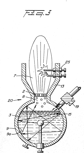
Figure 3 is a schematic illustration of the utilization of the structure of Figure 1.
-
Figure 8 is an array of exciters, such as shown in Figure 3, in a preferred embodiment.
-
In Figure 3 the resonant cavity structure 20 is utilized in a first completed self contained embodiment. Water 4 enters via nozzle 19 directly into the chamber of the closed sphere 9.
-
The structure of Figure 3 is substantially identical in operation to that of Figure 1. …
-
With reference to Figure 3, the port 2 is correlated in size of opening relative to the velocity of the gasses. If the port 2 is oversize the velocity of the gasses will be so great that a flame could not be sustained and backfire may occur, hence the port size is limited.
-
In Figure 7, the ports 57a to 57n may be greater in size that the individual port 2 of Figure 3. The individual outputs are not utilized to support a flame hence the significance of limiting the port size and the danger of flashback is not critical. The outputs from each of the exciters are accumulated as gasses 54 in a master chamber 58.
-
With particular reference now to Figure 8 there is illustrated an array of the gas exciters illustrated in Figure 3. The operation of the individual gas exciters is identical to that of Figure 3 except that in the array the several gas flames from the individual exciters are accumulated in chamber 75.
-
With particular reference now to Figure 8 there is illustrated an array of the gas exciters illustrated in Figure 3. The operation of the individual gas exciters is identical to that of Figure 3 except that in the array the several gas flames from the individual exciters are accumulated in chamber 75.