(39)
Opto-Coupler
Where it is first named
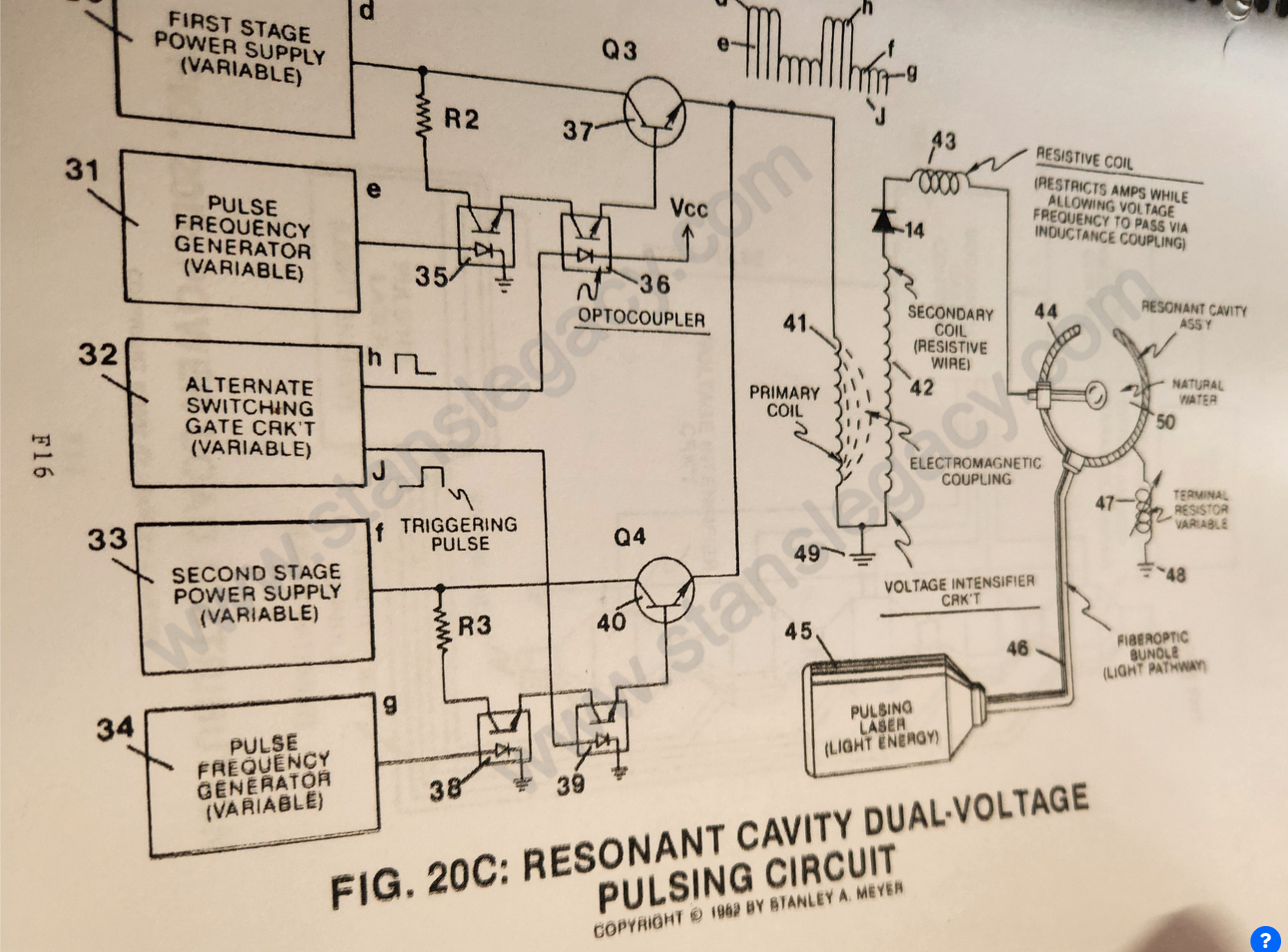
Integrating dual-pulsing circuit (33) (34) (38) (39) (40) to voltage intensifier circuit (Figure 9) previously described), as shown in Figure 20C.
How it is written
- (39) 3×
Drawings 2
-
Figure 20C · Resonant Cavity
-
Figure 20C · Resonant Cavity Mode of Operability
Where it is named · 3
Resonant Cavity 3×
-
opto-coupler (39)
Once said gate circuit (32) changes state (low to high voltage or versa), trigger pulse (J) turns on opto-coupler (39) to form voltage wave form (f) as to (g).