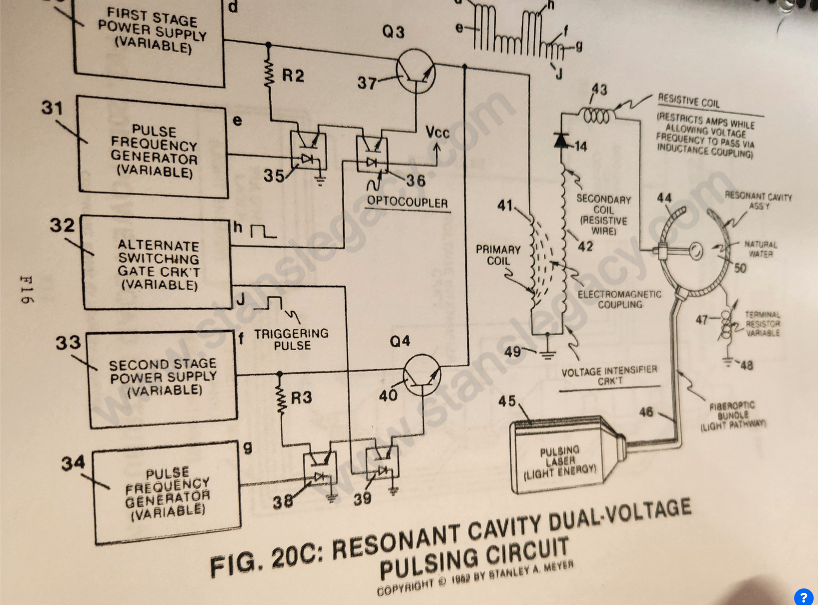
(32)
Gate Circuit
Also written variable gate circuit · gate control circuit
Where it is first named
As shown in Figure 20C. variable gate circuit (32) is a two-state switch device which is directly linked to both opto-coupler (36) and opto-coupler (39).
How it is written
- (32) 4×
Drawings 2
-
Figure 20C · Resonant Cavity
-
Figure 20C · Resonant Cavity Mode of Operability
Where it is named · 4
Resonant Cavity 4×
-
gate circuit (32)
Once said gate circuit (32) changes state (low to high voltage or versa), trigger pulse (J) turns on opto-coupler (39) to form voltage wave form (f) as to (g).
-
gate circuit (32)
Wave form (d) (e) and wave form (f) (g) now pulse-duty (52) which is varied from one duty-pulse one hundred duty-pulses (establishing pulse-train 51) via gate circuit (32) (tenth and eleventh steps to voltage attenuation).
-
gate control circuit (32)
To reduce the number of voltage pulses (53), simply reverse the pulse-train adjustment of said gate control circuit (32).