Figure (20)
Figure (20)
How it is written
- (20) 2×
Drawings 1
-
Beside the passage · Resonant Cavity Mode of Operability
On this figure 2
Where it is named · 2
Resonant Cavity Mode of Operability 2×
-
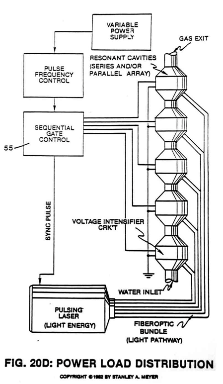
8. To increase and encourage greater particle collision (particle impact), accelerator tube (56) of Figure (20A) is placed between said resonant cavity stages (see Figure 20 and 20D).
-
Increasing particle velocity directly increases gas yield to the next resonant cavity stage. Adding more accelerator tubes (56a through 56n of Figure 20B) per resonant cavity stage (see Figure 20) increases gas yield still further (see Figure 20B again).