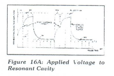
(44)
Electrical Voltage Zones
Also written voltage zones · Resonant Cavity Outer Surface · Voltage zones surface area · Resonant Cavity Assembly · negative voltage zone · capacitive reactance
Where it is first named
Resonant Cavity Outer Surface (44) (forming a Negative Voltage Zone)
How it is written
- (44/45) 4× with (45) Voltage zones surface area
- (44) 2×
- (44/47) 1× with (47) Resonant Charging Choke
Drawings 2
-
Electrical Voltage Zones (44/45) · Dual Voltage Resonant "Q" - Part 2
-
The figure it sits on · DUAL VOLTAGE RESONANT "Q"
Where it is named · 7
DUAL VOLTAGE RESONANT "Q" 4×
-
Resonant Cavity Outer Surface (44)
Resonant Cavity Outer Surface (44) (forming a Negative Voltage Zone)
-
Voltage zones surface area (44/45)
Voltage zones surface area (44/45) form the Capacitance value of said Resonant Cavity Assembly (4) of Figure 12. Natural Water inside said Resonant Cavity Assembly (44/45) provides the dielectric value between said voltage zones (44/45), resonant charging choke (47) to electrical ground forms and completes the Voltage Intensifier Circuit 9XA as to 20YA.
-
Resonant Cavity Assembly (44/45)
Voltage zones surface area (44/45) form the Capacitance value of said Resonant Cavity Assembly (4) of Figure 12. Natural Water inside said Resonant Cavity Assembly (44/45) provides the dielectric value between said voltage zones (44/45), resonant charging choke (47) to electrical ground forms and completes the Voltage Intensifier Circuit 9XA as to 20YA.
-
voltage zones (44/45)
Voltage zones surface area (44/45) form the Capacitance value of said Resonant Cavity Assembly (4) of Figure 12. Natural Water inside said Resonant Cavity Assembly (44/45) provides the dielectric value between said voltage zones (44/45), resonant charging choke (47) to electrical ground forms and completes the Voltage Intensifier Circuit 9XA as to 20YA.
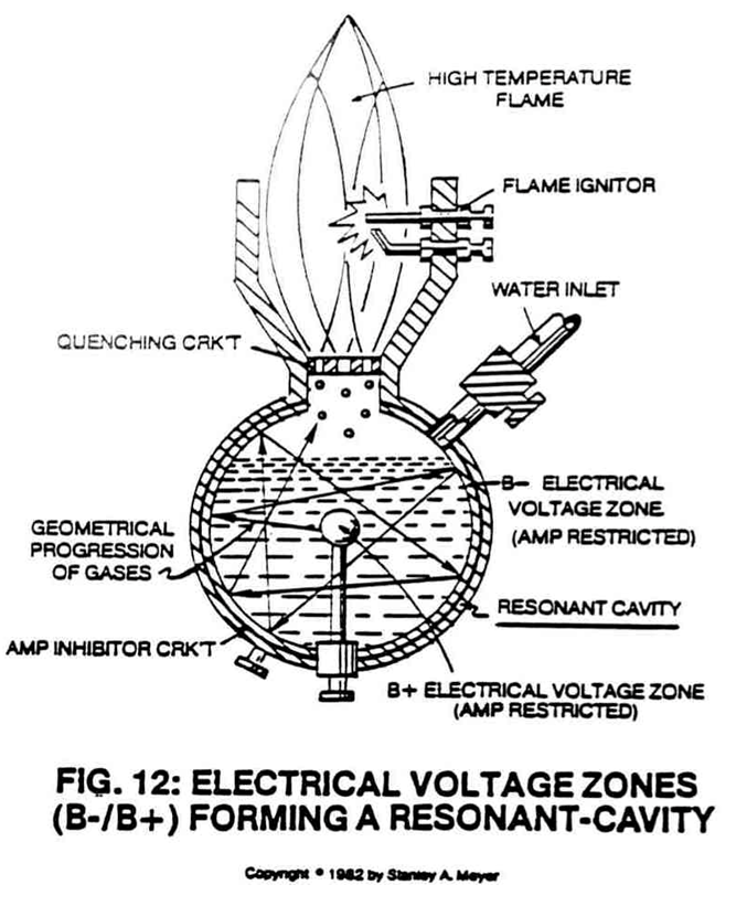
Dual Voltage Resonant "Q" - Part 2 3×
-
capacitive reactance (44/47)
Resonant Action occurs when the Voltage Intensifier Circuit 9XA as to 20YA set up a circuit condition whereby the inductive (43/45) and capacitive reactance (44/47) (or circuit impedance) components of said circuit have been balanced.