Figure (6A)
Figure (6A)
How it is written
- (6A) 8×
Drawings 2
-
FIGURE 6A · Process & Apparatus For The Production Of Fuel Gas & The Enhanced Release Of Thermal Energy From Such Gas
On this figure 1
Where it is named · 8
Process & Apparatus For The Production Of Fuel Gas & The Enhanced Release Of Thermal Energy From Such Gas 8×
-
FIGURE 6A
-
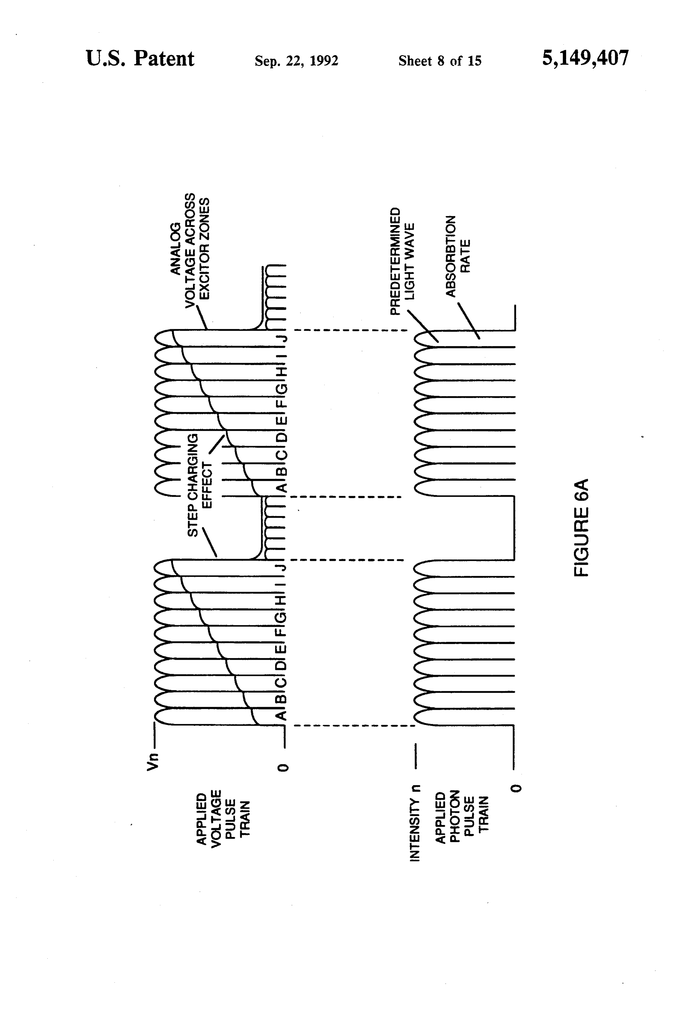
FIGS. 6A, 6B, 6C and 6D are illustrations depicting various theoretical bases for atomic phenomena expected to occur during operation of the invention herein.
-
Once triggered, the thermal explosive energy output is controllable by the attenuation of operational parameters. With reference to FIG. 6A, for example, once the frequency of resonance is identified, by varying applied pulse voltage to the initial water fuel cell assemblies, 2, 3, the ultimate explosive energy output is likewise varied. By varying the pulse shape and/or amplitude or
-
… 7 provides a pulsating, polar electric field to the gas mixture as illustrated in FIG. 6A, whereby electrons of the gas atoms are distended in their orbital fields by reason of their subjection to electrical polar forces, changing from the state conceptually
-
… When a unipolar voltage pulse train such as shown in FIG. 6A (53a xxx 53”) is applied, an increasing voltage potential is induced in the molecules, gases and/or ions in a linear, step-like charging effect. …
-
cal field plates increases from a low energy state (A) to a high energy state (J) in a step manner following each pulse-train as illustrated in FIG. 6A. …
-
… the potential difference applied causes the orientated water molecules to align themselves between the conductive plates, pulsing causes the voltage field intensity to be increased in accordance with FIG. 6A. …
-
The repetitive application of a voltage pulse train (A through J of FIG. 6A) incrementally achieves the critical state of said gas ions. …