Figure (5A)
Figure (5A)
How it is written
- (5A) 12×
Drawings 1
-
FIGURE 5A · Process & Apparatus For The Production Of Fuel Gas & The Enhanced Release Of Thermal Energy From Such Gas
On this figure 3
Where it is named · 12
Process & Apparatus For The Production Of Fuel Gas & The Enhanced Release Of Thermal Energy From Such Gas 12×
-
FIGURE 5A
-
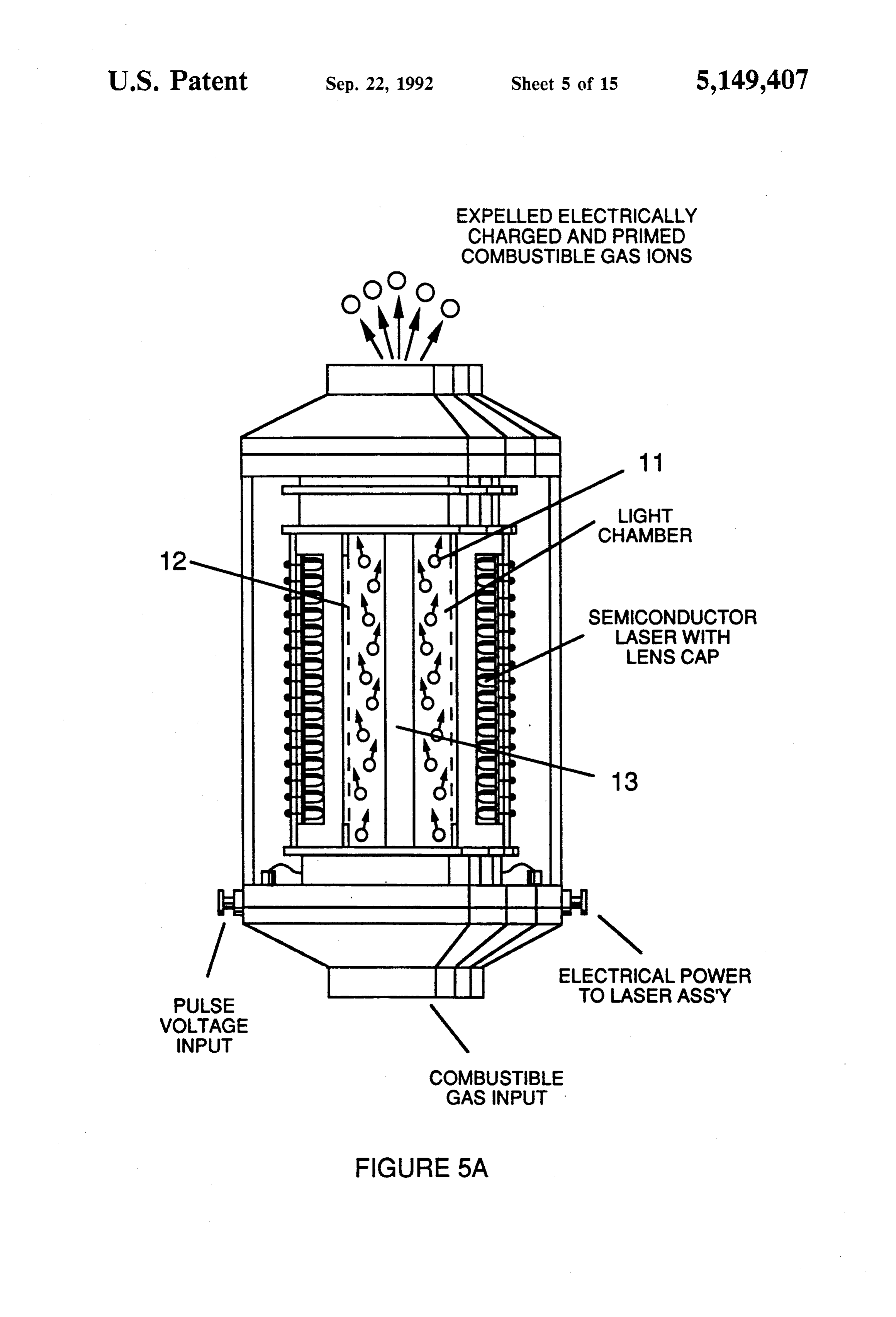
FIG. 5A shows a cross-section of a circular gas resonant cavity used in the final stage assembly of FIG. 4.
-
… In a final stage, an injector system 4, of a configuration of the type shown in FIGS. 5A or 5B, receives energized atomic and gas particles where the particles are subjected to further energy input, electrical excitation and thermal stimulation, whereby thermal explosive energy results 5, which may be directed thru a lens assembly of the type shown in FIG. …
-
The gas ions within the wave energy chamber are subjected to an oscillating high intensity voltage field in a chamber 11 in FIGS. 5A and 5B formed within electrodes 12 and 13 in FIGS. 5A and 5B of opposite electrical polarity to produce a resonant cavity. The gas ions reach a critical energy state at a resonant state.
-
The gas ions within the wave energy chamber are subjected to an oscillating high intensity voltage field in a chamber 11 in FIGS. 5A and 5B formed within electrodes 12 and 13 in FIGS. 5A and 5B of opposite electrical polarity to produce a resonant cavity. The gas ions reach a critical energy state at a resonant state.
-
… At this point electrons are extracted from the chamber by a grid system such as shown in FIG. 5A. …
-
… A longitudinal cross section of a gas resonant cavity is Shown in FIG. 5A. …
-
… In the device of FIG. 5A, semiconductor optical lasers 20a-20p, 20xxx surround the gas flow path. …
-
… 8A and 8B, is applied to the assembly of FIG. 5A or FIG. …
-
… 8A) is placed in spaced relationship to the gas resonant cavity structure shown in FIG. 5A. …