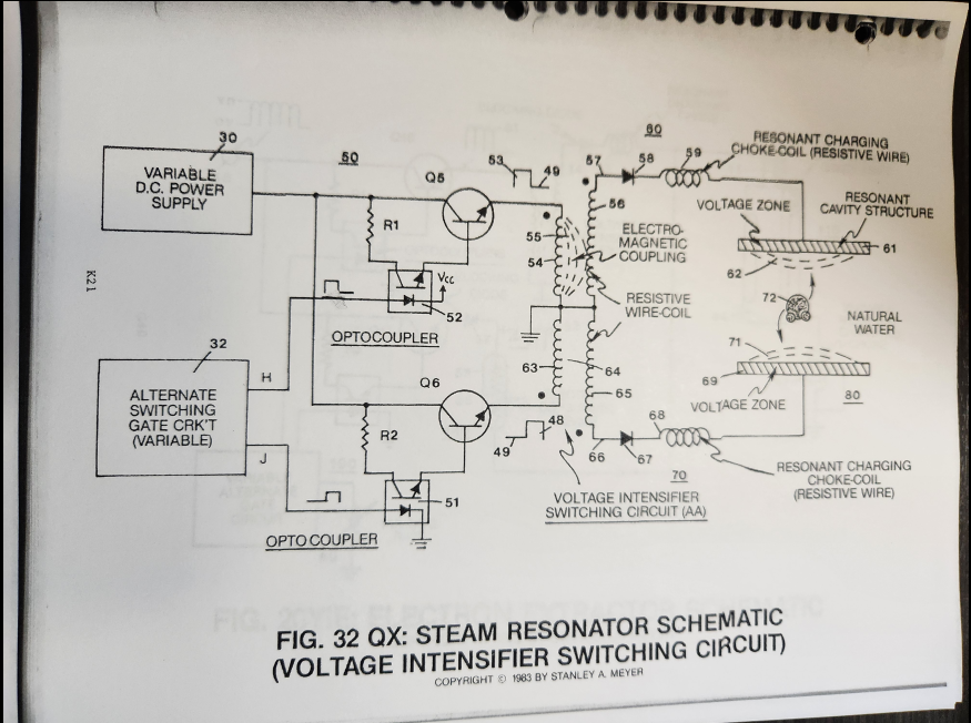
(AA)
Voltage Intensifier Switching Circuit
Where it is first named
Integrating alternate pulsing circuit (Q5) as to (Q6) to said voltage intensifier switching circuit (AA) arranged in a dual polarity configuration, as illustrated in Figure 32QX titled Steam Resonator Schematic.
How it is written
- (AA) 4×
Drawings 1
-
Beside the passage · Steam Resonator
Where it is named · 4
Steam Resonator 4×
-
Voltage Intensifier Switching Circuit (AA)
Repeating said alternate gate switching (H) as to (J) applies an alternate duty pulse of positive polarity to said Voltage Intensifier Switching Circuit (AA), as shown in Figure 32QX.
-
Voltage Intensifier Switching Circuit (AA)
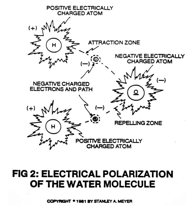
Dual pulsing circuit (50) linked to said Voltage Intensifier Switching Circuit (AA) simply switches or alternates a unipolar positive voltage pulse from one Excitor Plate (61) to another Excitor Plate (69) in a sequential manner to produce superheated steam by way of voltage deflection of the water molecule.