(LC)
Inductor-Capacitor Circuit
Also written Plate Inductance
Where it is first named
F = 1 / (2π √(LC))
How it is written
- (LC) 5×
- (Lc) 1×
Drawings 13
-
Stanley A. Meyer Page_2 of 28 · WFC 417 — WFC 417
-
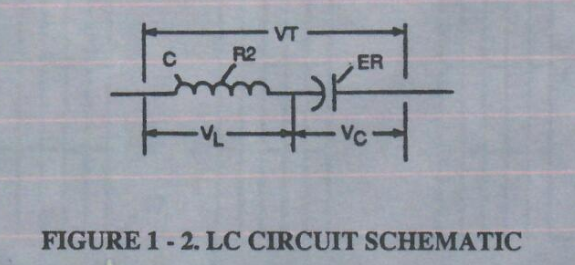
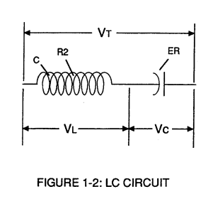
LC CIRCUIT Figure 1-2. LC Circuit Schematic · CIRCUIT COMPONENT INTERACTION
-
LC CIRCUIT Figure 1-2. LC Circuit Schematic · CIRCUIT COMPONENT INTERACTION
-
Figure (1-2) · LC Circuit
-
The figure it sits on · Water Fuel Injection System
-
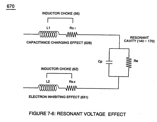
(670) of Figure (7-6) · Inductance (FL)
-
(670) of Figure (7-6) · Capacitance (Cd)
-
(670) of Figure (7-6) · Capacitance (Cd)
-
The figure it sits on · Taper Resonant Capacitor (ERt)
-
Resonant Capacitor (140 -170) of Figure (7-6) · Capacitance Reactance
-
Resonant Voltage Effect (670) of Figure (7-6) · Transformer Action
-
The figure it sits on · WFC 426 - Illustrations
-
The figure it sits on · Dual Switchover Circuit
Where it is named · 6
The equations of The Birth of New Technology, typed 2×
-
F = 1 / (2π √(LC))
-
F = 1 / (2π √(LC))
WFC 417 — WFC 417 1×
-
Resonant Charging Choke (c) in series with Excitor-array (E1/E2) forms an inductor-capacitor circuit (LC) since the Excitor-Array (ER) acts or performs as an capacitor during pulsing operations.
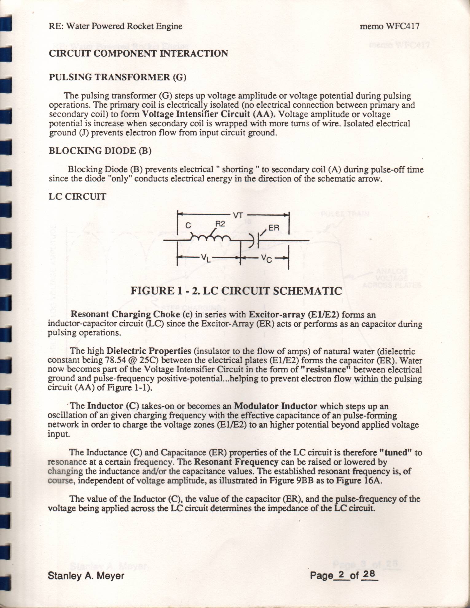
CIRCUIT COMPONENT INTERACTION 1×
-
inductor-capacitor circuit (LC)
Resonant Charging Choke (c) in series with Excitor-array (E3/E4) forms an inductor-capacitor circuit (LC) since the Excitor-Array (ER) of Gas Resonant Cavity (t) acts or performs as a capacitor during pulsing operations.