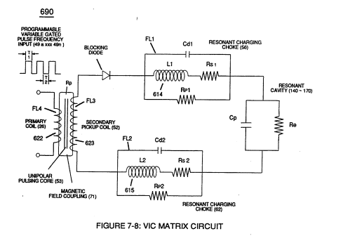
(Rp2) · also written as a run, Rp2a xxx Rp2n
Mutual Inductance Fields
Also written excitation External Magnetic Field · External Magnetic Field
Where it is first named
… nce" (FL1a xxx FL1n = FL2a xxx FL2n) of said "Bifilar" wrapped coils encourages the compounding effect (increasing magnetic field-strength during each pulsing cycle) of electromagnetic field-strength (Rpla xxx Rpin = Rp2a xxx Rp2n) (mutual induction) when applied Pulse-Voltage Frequency (49a xxx 49n) passes through the positive energized Resonant Charging Choke (56).
How it is written
- (Rp1/Rp2) 4× with (Rp1) Coupling Inductance
- (Rp2) 3×
- (Rp1a xxx Rp1n - Rp2a xxx Rp2n) 1× with (Rp1) Coupling Inductance
- (Rpla xxx Rpin = Rp2a xxx Rp2n) 1× with (Rpl) Mutual Inductance Fields, (Rpi)
- (Rpl + Rp2) 1× with (Rpl) Mutual Inductance Fields
- (Rpl/Rp2) 1× with (Rpl) Mutual Inductance Fields
Rp2a xxx Rp2n is Meyer's shorthand for a run of the same thing: Rp2a is the first, Rp2n the last, and the x's stand for however many lie between. Every stage of the run is this one numeral. A pair before the letters, 583/602a, is a run of two things that go together, one of each per stage.
Drawings 34
-
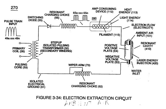
(270) of Figure (3-34) · Gas Processor
-
The figure it sits on · WFC 422DA - Illustrations
-
(270) of (3-34) · In Application of Usage
-
coil-structures (580) of Figure (6-1) · Voltage Intensifier Coil-Assembly
-
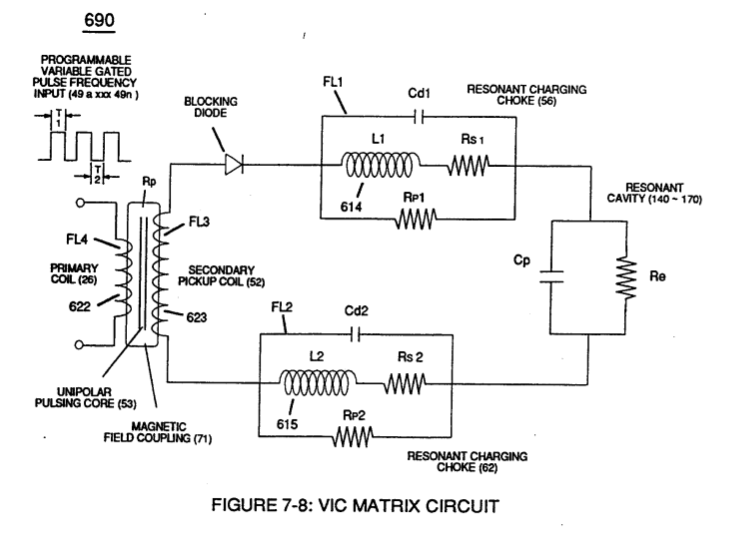
The figure it sits on · VIC Matrix Circuit
-
(T2) of Figure (7-8) · Instant Explosion of Water
-
Figure (7-8) · Resistance (Rs)
-
(690) of Figure (7-8) · Resistance (Rs)
-
(580) of Figure (6-1) · Inductance (FL)
-
(690) of Figure (7-8) · Inductance (FL)
-
(750) of Figure (7-14) · Inductance (FL)
-
(750) of Figure (7-14) · Capacitance (Cd)
-
(690) of Figure (7-8) · Capacitance (Cd)
-
(690) of Figure (7-8) · Inductance Reactance (Rs - Cd - FL)
-
(750) of Figure (7-14) · Inductance Reactance (Rs - Cd - FL)
-
Figure (7-8) · Inductance Reactance (Rs - Cd - FL)
-
(580) of Figure (6-1) · Multi-layer Coil
-
(690) of Figure (7-8) · Taper Resonant Capacitor (ERt)
-
690 of Figure 7-8 · Circuit Resistance
-
(52) of Figure (7-8) · Electron Bounce Phenomenon
-
Voltage Graph (750) of Figure (7-14) · Electron Bounce Phenomenon
-
The figure it sits on · WFC 426 - Illustrations
-
(580) of Figure (6-1) (WFC memo 425) · 8-2 - Traveling Voltage Wave-Guides
-
(690) of Figure (7-8) · 8-2 - Traveling Voltage Wave-Guides
-
(52) of Figure (7-8) · 8-3 - Electrical Voltage-Pulse Wave-Transmission
-
(Cp) of Figure (7-8) · 8-4 - State Space (Sp)
-
(690) of Figure (7-8) · 8-6 - VIC Voltage Sync-Pulse Circuit
-
(Cp) of (7-8) · 8-6 - VIC Voltage Sync-Pulse Circuit
-
(690) of Figure (7-8) · Propagating Electrical Stress
-
Figure (3-34) · Propagating Electrical Stress
-
(580) of Figure (6-1) · Voltage to Amp Differential Ratio
-
blocking diode (55) of Figure (3-34) · Voltage to Amp Differential Ratio
-
Voltage Performance Graph (750) of Figure (7-14) · Voltage to Amp Differential Ratio
-
The figure it sits on · WFC 429 - Illustrations
Where it is named · 11
Amp Inhibiting Circuit Vs Voltage Enhancement 1×
-
… nce" (FL1a xxx FL1n = FL2a xxx FL2n) of said "Bifilar" wrapped coils encourages the compounding effect (increasing magnetic field-strength during each pulsing cycle) of electromagnetic field-strength (Rpla xxx Rpin = Rp2a xxx Rp2n) (mutual induction) when applied Pulse-Voltage Frequency (49a xxx 49n) passes through the positive energized Resonant Charging Choke (56).
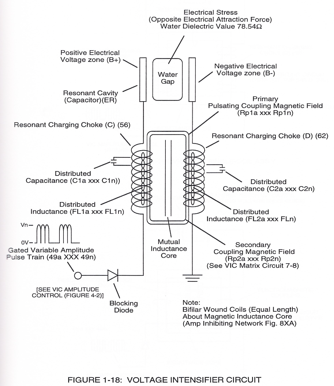
Inductance Reactance (Rs - Cd - FL) 1×
-
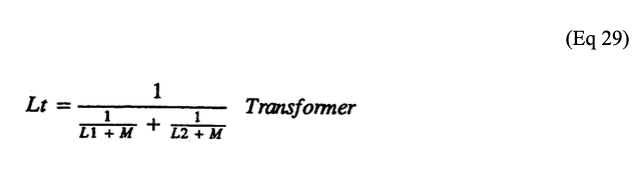
… ng-Core (190) of Figure (3-23) as to VIC Coil Assembly (580) of Figure (6-1) enters into and passes through both Inductors (L1/L2) simultaneously and offers not only further electron-flow restriction (Rp1/Rp2) to both Inductor Chokes (56/62) but automatically increases voltage potential (xxx V g xxx Vh xxx Vn) of opposite voltage intensity of equal magnitude (66/67) across Resonant Cavity (140 -170)
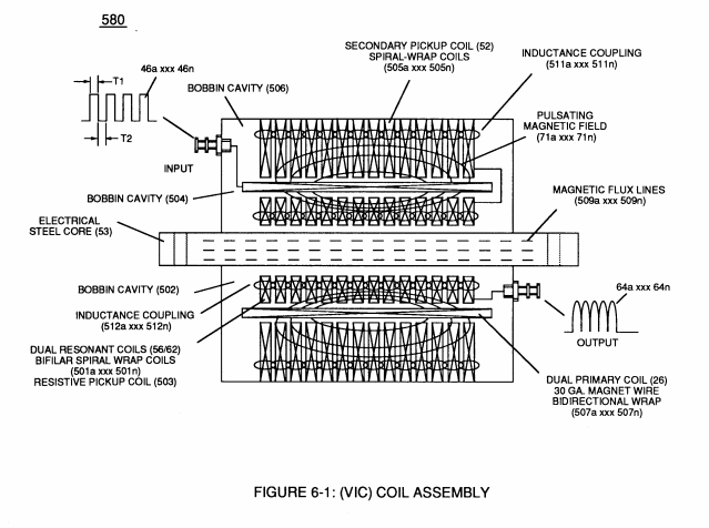
Transformer Action 2×
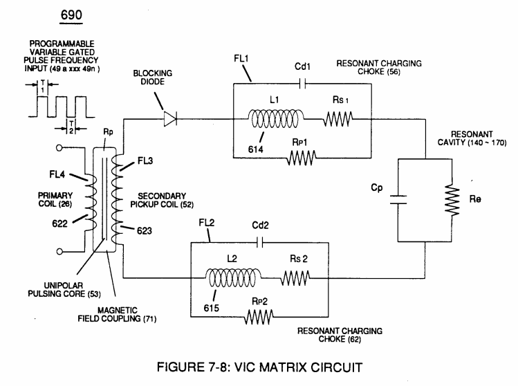

Electron Bounce Phenomenon 2×
Propagating Electrical Stress 3×
-
Mutual Inductance Fields (Rpl/Rp2)
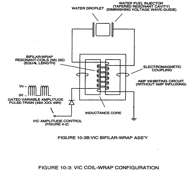
VIC Bifilar Wrap Coil-Assembly (10-3B) and VIC Dual Coil Wrap-Assembly (10-3A) both utilize either "E" & “I” and "U" Inductance Core configurations to concentrate Mutual Inductance Fields (Rpl/Rp2) in order to optimize Amp Inhibiting Process (750) of Figure (7-14).
-
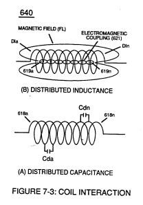
… id "bifilar" wrapped coils (Figure 7-3) as to (990) of Figure (10-3) encourages the compounding effect (increasing magnetic field-strength during each pulsing cycle) of electromagnetic field-strength (Rp1a xxx Rp1n - Rp2a xxx Rp2n) (mutual induction) when applied Pulse-Voltage frequency (49a xxx 49n) of Figure (3-34) passes through the positive energized Resonant Charging Choke (56).
Voltage to Amp Differential Ratio 2×
-
… oil-wire length is longer than the Stainless steel coil-wire length and magnet bifilar-coil (56/62) is placed on top of Stainless Steel bifilar-coil (SS56/62) to maximize mutual inductance coil-field (Rp2) (adding Rp1+Rp2) of (690) of Figure (7-8) to cause coil capacitance (Cda xxx Cdn) to help maintain and even increase pulse voltage amplitude (xxx Vn + Vn 1 + Vn2 + Vn .... …
-
… etc.) while the resistive value (Rs2) of SS Coil-Wire (SS56/62) performs the work of further resisting the flow of amps not inhibited by both self-Inductance fields (Rpl + Rp2), as so illustrated in (690) of Figure (7-8).