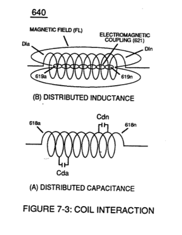
(Cd) · also written as a run, Cda xxx Cdn
Distributed capacitance
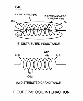
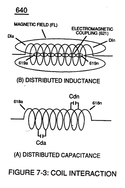
The capacitance inherent in each of the inductance coils (52 - 56 - 62), Figure 7-3. On the Electron Bounce page mutual inductance (M), equations 28 to 30, transforms it into one coherent voltage potential (Vo ... Vn) equal to the sum of the potentials (Vp) developed across each pickup coil.
How it is written
- (Cda xxx Cdn) 6×
- (Cd) 1×
- (Cda xxx Coo) 1× with (Coo)
Cda xxx Cdn is Meyer's shorthand for a run of the same thing: Cda is the first, Cdn the last, and the x's stand for however many lie between. Every stage of the run is this one numeral. A pair before the letters, 583/602a, is a run of two things that go together, one of each per stage.
Drawings 26
-
Distributed Capacitance (Cda xxx Cdn) of Figure (7-3) · Electron Bounce Phenomenon
-
Distributed Capacitance (Cda xxx Cdn) of Figure (7-3) · Electron Bounce Phenomenon
-
The figure it sits on · VIC Matrix Circuit
-
(T2) of Figure (7-8) · Instant Explosion of Water
-
(FI) of Figure (7-3b) · Instant Explosion of Water
-
Figure (7-8) · Resistance (Rs)
-
(690) of Figure (7-8) · Resistance (Rs)
-
(690) of Figure (7-8) · Inductance (FL)
-
Figure (7-3) · Inductance (FL)
-
(690) of Figure (7-8) · Capacitance (Cd)
-
(690) of Figure (7-8) · Inductance Reactance (Rs - Cd - FL)
-
Figure (7-8) · Inductance Reactance (Rs - Cd - FL)
-
Figure (7-3) · Multi-layer Coil
-
(690) of Figure (7-8) · Taper Resonant Capacitor (ERt)
-
690 of Figure 7-8 · Circuit Resistance
-
(52) of Figure (7-8) · Electron Bounce Phenomenon
-
The figure it sits on · WFC 426 - Illustrations
-
(690) of Figure (7-8) · 8-2 - Traveling Voltage Wave-Guides
-
(52) of Figure (7-8) · 8-3 - Electrical Voltage-Pulse Wave-Transmission
-
(Cp) of Figure (7-8) · 8-4 - State Space (Sp)
-
(690) of Figure (7-8) · 8-6 - VIC Voltage Sync-Pulse Circuit
-
(Cp) of (7-8) · 8-6 - VIC Voltage Sync-Pulse Circuit
-
(690) of Figure (7-8) · Propagating Electrical Stress
-
"bifilar" wrapped coils (Figure 7-3) · Propagating Electrical Stress
-
The figure it sits on · WFC 429 - Illustrations
-
The figure it sits on · VIC Switchover Circuit
Where it is named · 8
Inductance (FL) 1×
-
Distributed Capacitance (Cda xxx Cdn)
... interacting Distributed Capacitance (Cda xxx Cdn) and Distributed Inductance (D1a xxx D1n) of Figure (7-3) of Inductor Coil (614) of (7-1) with "Electrical Charging Effect" brought on by the dielectric value of water bath (85/Re), as pictorially illustrated in (650) of Figure (7-4).
Capacitance (Cd) 1×
-
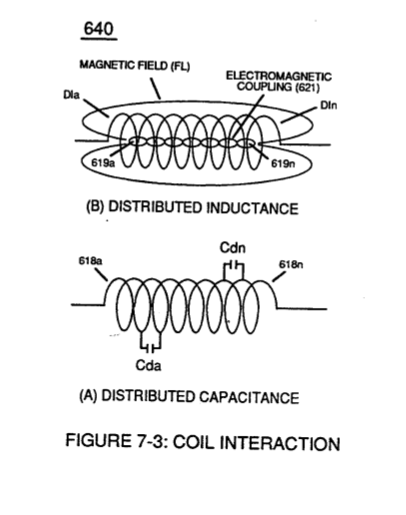
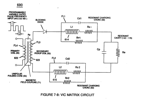
The circular-spiral turns of wire (forming parallel electrical surfaces) is separated by an Insulated Dielectric Coating Material which forms a series of capacitors (Cda xxx Cdn) when magnetic flux-lines (619a xxx 619n) produce Electromagnetic Coupling Field (621) during pulse on-time (T1), as illustrated in (640) of Figure (7-3) as to (690) of Figure (7-8).
Inductance Reactance (Rs - Cd - FL) 1×
-
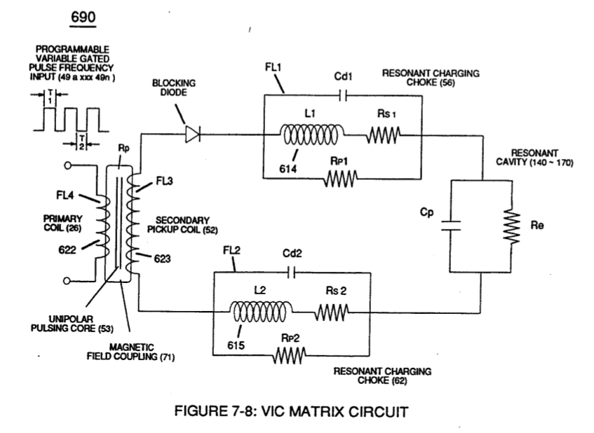
Inductance Reactance occurs when resistance (Rs), capacitance (Cd), and Inductance (FL) interacts together during D.C. Pulsing (49a xxx 49n), as schematically depicted in (690) of Figure (7-8).
Multi-layer Coil 1×
-
Inductance of a multi-layer coil of rectangular cross section can be computed by below formula when optimizing maximum distributed capacitance (Cda xxx Coo) and distributed inductance (Dla xxx Dln) of Figure (7-3) to intensify Inductance Field Strength (FLa xxx FLn) to function as a voltage multiplier in switch-off conditions (612a xxx 612n), as illustrated in (710) of ~ . …
Electron Bounce Phenomenon 2×
-
Distributed Capacitance (Cda xxx Cdn)
.... causing mutual inductance (μ1) (see equations Eq 28 thru Eq 30) to transform Distributed Capacitance (Cda xxx Cdn) of Figure (7-3) of each inductance coils (52 - 56 - 62) into a coherent Voltage Potential (Yo •..• Vn) equaling the sum of Voltage Potential (Vp) developed across each Pickup Coils (VpT + Vp1 + Vp2)
-
Distributed Capacitance (Cda xxx Cdn)
Distributed Capacitance (Cda xxx Cdn) of Figure (7-3)
Voltage to Amp Differential Ratio 1×
-
… gnet bifilar-coil (56/62) is placed on top of Stainless Steel bifilar-coil (SS56/62) to maximize mutual inductance coil-field (Rp2) (adding Rp1+Rp2) of (690) of Figure (7-8) to cause coil capacitance (Cda xxx Cdn) to help maintain and even increase pulse voltage amplitude (xxx Vn + Vn 1 + Vn2 + Vn .... …
VIC Switchover Circuit 1×
-
distributed capacitance (Cda xxx Cdn)
While, the distributed capacitance (Cda xxx Cdn) of each coil experiencing inductance coupling (619) elevates applied voltage level (Vn) to a higher voltage amplitude (increasing voltage intensity) required to deflect the bipolar water molecule to a given or pre-selected distance.