(VL)
Voltage Intensity
Also written constant voltage level
Where it is first named
Printed: WFC 420, page 1-3, in the chapter [[doc:@bookstack/388|LC Voltage]]. Meyer's terms: The voltage (VL) across the inductor (C). …
How it is written
- (VL ~ Vn xxx) 3× with (V) Voltage potential
- (VL) 2×
- (xxx VL xxx) 2×
- (VL xx Va) 1× with (V) Voltage potential
- (xxx VL = Vn) 1× with (V) Voltage potential
- (xxxx VL) 1×
Drawings 3
-
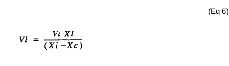
The voltage (VL) across the inductor (C) is given by the equation (Eq 6) · LC Voltage
-
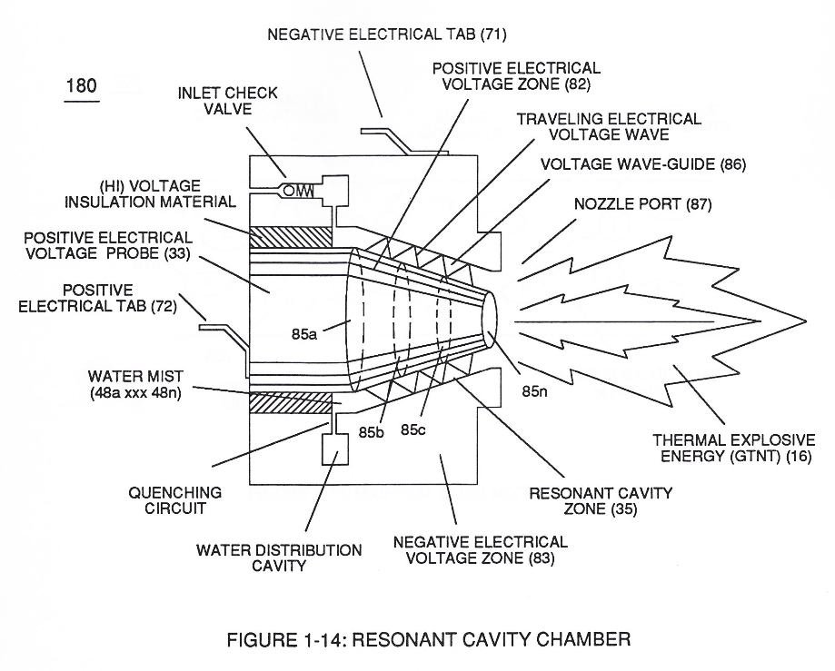
Figure (17) · Water Fuel Injector (Taper Resonant Cavity Chamber)
-
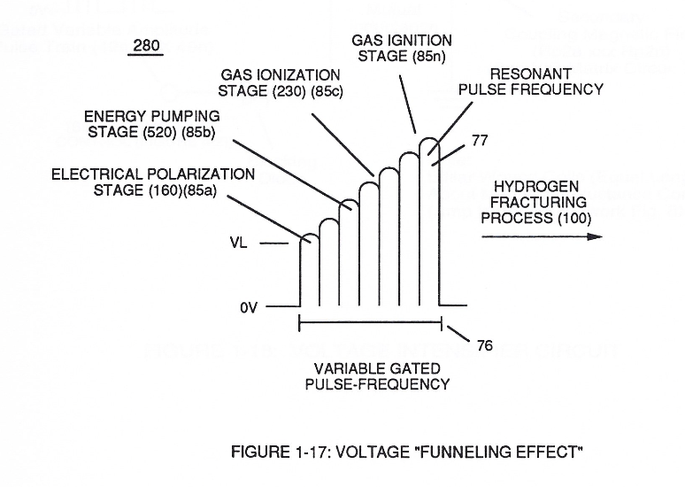
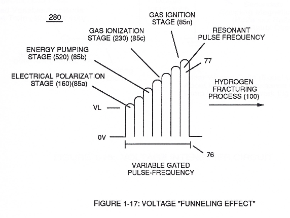
Beside the passage · Funneling Effect
Where it is named · 10
The equations of The Birth of New Technology, typed 1×
-
Printed: WFC 420, page 1-3, in the chapter [[doc:@bookstack/388|LC Voltage]]. Meyer's terms: The voltage (VL) across the inductor (C). …
LC Voltage 1×
-
The voltage (VL) across the inductor (C) is given by the equation (Eq 6)
Water Fuel Injector (Taper Resonant Cavity Chamber) 3×
-
This further increase in voltage amplitude (xxxx VL) simply exerts a greater magnitude of opposite Electrical-Stress (SS'-RR') of Figure (25) (TT' - UU') of Figure (29) (WFC Memo 422 DA) across combustible gas atoms (76, 77a - 77b)
Funneling Effect 5×
-
This resultant "Funneling Effect" (260), now, allows voltage amplitude (Vn) wave-form (58) to travel the length of Resonant Cavity Zone (35) from Start-Point (85a) to End-Point (85n) increasing voltage intensity (xxx VL = Vn) as parallel voltage surfaces (83/84) diminishes in size relationship (85a ~ 85n), as illustrated in (210) of Figure (17).
-
In alternate form, Core-Slug (73) is replaced by a series of Choke Coils (77a xxx 77n) arranged in such a way as to increase voltage Intensity (Voltage Pulse Amplitude) (VL ~ Vn xxx) digitally by sequentially switching-on / switching -off Choke Coils (77a xxx 77n) to allow applied Voltage Intensity (VL ~ Vn xxx) to be placed across Voltage Expander Coils (78a xxx 78n) in direct r …
-
Voltage Intensity (VL ~ Vn xxx)
… uch a way as to increase voltage Intensity (Voltage Pulse Amplitude) (VL ~ Vn xxx) digitally by sequentially switching-on / switching -off Choke Coils (77a xxx 77n) to allow applied Voltage Intensity (VL ~ Vn xxx) to be placed across Voltage Expander Coils (78a xxx 78n) in direct relationship to electrically energized shunt-coil (76).
-
Voltage Intensity (VL ~ Vn xxx)
For example, as adjacent Shunt-Coil (76b) is switch-on while, simultaneously, Choke Coil (76a) is switch-off by Electronic Switch Circuit (79), Voltage Intensity (VL ~ Vn xxx) is increased due to inductance / capacitance of Voltage Expander Coil (78a) which is, now, added to Electrical Circuit (250) by electrical pathway (82a) since electromagnetic coupling field (76b) pre …