Figure (10)
Figure (10)
How it is written
- (10) 13× with (10) Heat Insulation Barrier
Drawings 7
-
10. The multi-stage solar system of claim 1'wherein said deflection vanes can be uniformly, alternately, or · MultiStage Solar Storage System
-
10 Claims, 23 Drawing Figures · MultiStage Solar Storage System
-
Page 11 · MultiStage Solar Storage System
-
Page 12 · MultiStage Solar Storage System
-
Page 26 · MultiStage Solar Storage System
-
Page 27 · MultiStage Solar Storage System
-
Page 28 · MultiStage Solar Storage System
On this figure 2
Where it is named · 13
MultiStage Solar Storage System 13×
-
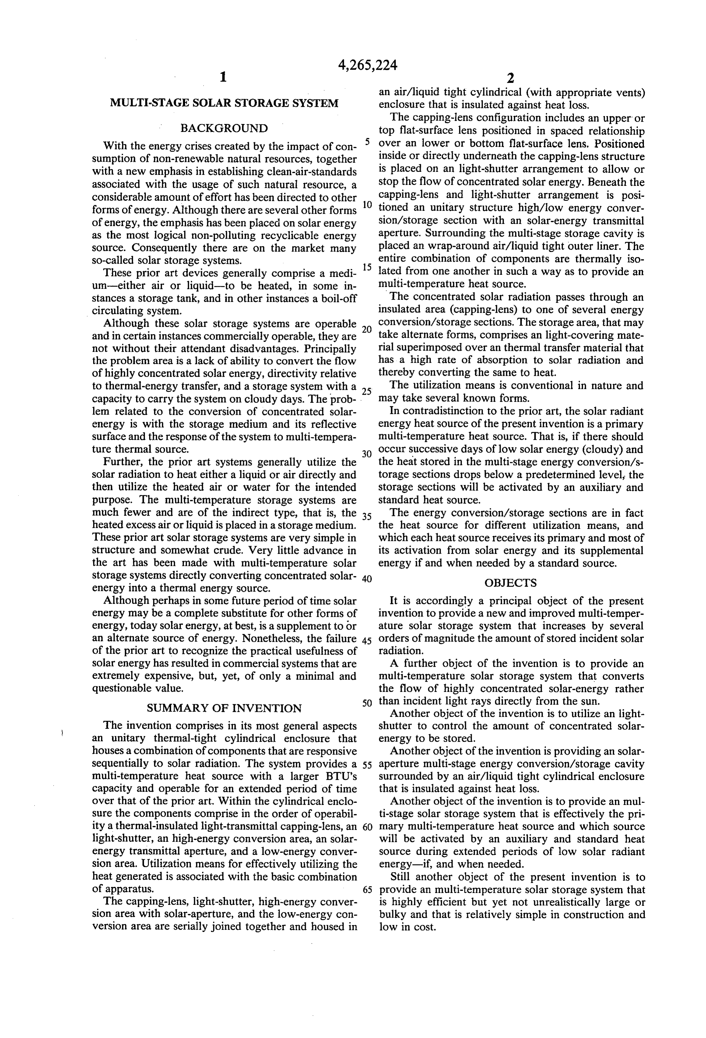
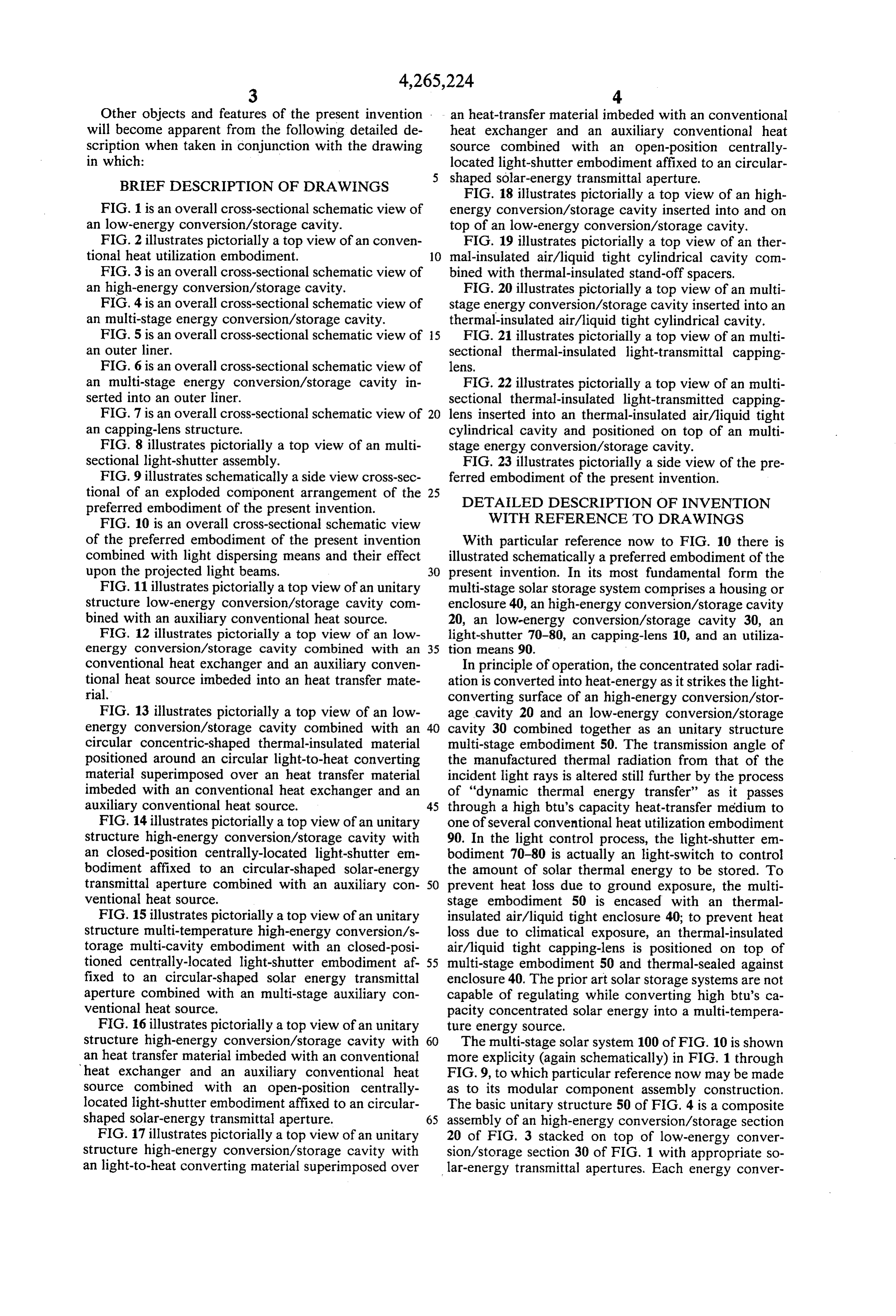
FIG. 10 is an overall cross-sectional schematic view of the preferred embodiment of the present invention combined with light dispersing means and their effect upon the projected light beams.
-
With particular reference now to FIG. 10 there is illustrated schematically a preferred embodiment of the present invention. In its most fundamental form the multi-stage solar storage system comprises a housing or enclosure 40, an high-energy conversion/storage cavity 20, an low-energy conversion/storage cavity 30, an light-shutter 70-80, an capping-lens 10, and an utilization means 90.
-
The multi-stage solar system 100 of FIG. 10 is shown more explicity (again schematically) in FIG. …
-
… 4 as illustrated in 100 of FIG. 10. …
-
Referring now to FIG. 10, there is illustrated schematically the operational principle of the present invention in its most simplified embodiment, The incoming incident light rays (concentrated light energy derived from a so …
-
… Relative to the angle of the incoming light 2a xxx 2n and 3a xxx 3u, the light rays will be converted into thermal radiation and thereafter transmitted therefrom as angular displaced heat rays 4a xxx 4 and 5a xxx 5” as illustrated in FIG. 10. …
-
In actual operation, then, the storage area 20-30 is the multi-heat source with a given capacity and the extremely efficient multi-stage solar storage system 100 of FIG. 10 does generate and retain an extremely larger amount of thermal energy hereintofore not possible with the prior solar storage systems.
-
… 1 as shown in 100 in FIG. 10 is activated. …
-
In terms of constant utilization, the multi-stage solar storage system 100 of FIG. 10 can now be synchronized with the cycling sun (sunrise-to-sunset, cloudy-to-sunny days) in such a way as to provide a continuous multitemperature heat source until the absent sunshine becomes available once again to recharge the system for further duty loading. …
-
… Consequently, the multi-temperature heat source derived from multi-stage solar storage system 100 of FIG. 10 can be simultaneously utilized for electrical power generation, space heating, and hot water heating for the home or commercially without heat-supply failure—eliminating the need for conventional f …
-
The overall construction of the multi-stage solar stor- ° age system 100 of FIG. 10 of the present invention may take most any geometrical configuration—square, rectangular, oval, contoured, etc.. …
-
and inserted into earth-ground 45 as shown in FIG. 10 for unit stabilization.
-
FIG. 1 through FIG. 10 are aforesaid schematic in cross-sectional view to illustrate the function and operation of the present invention.