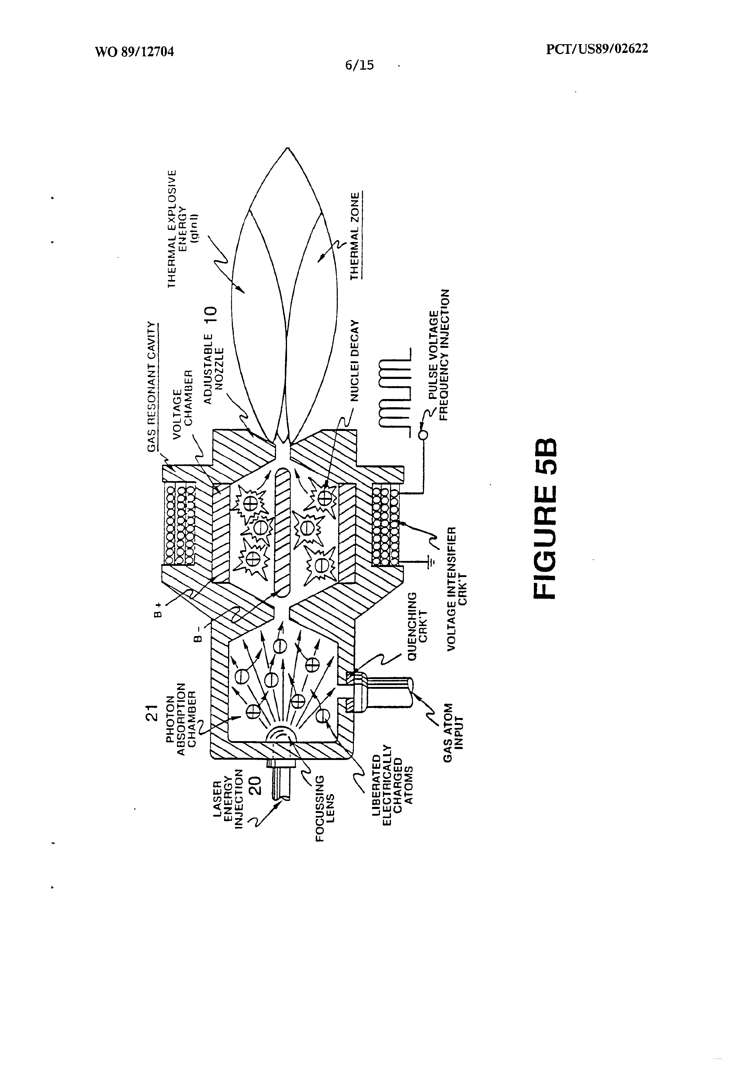
Figure (5B)
Figure (5B)
How it is written
- (5B) 9×
Drawings 1
On this figure 2
Where it is named · 9
Process And Apparatus For The Production Of Fuel Gas And The Enhanced Release Of Thermal Energy From Such Gas 9×
-
Figure 5B shows an alternative final stage injection system useful in the apparatus of Figure 4.
-
Figures 8A and 8B, respectively, show (A) an electron extractor grid used in the injector assemblies of Figure 5A and Figure 5B, and (B) the electronic control circuit for the extractor grid.
-
… A nozzle, 10 in Figure 5B, or thermal lens assembly, Figure 5C, provides the directing means in which the destabilized ions are finally thermally ignited.
-
… In the device of Figure 5B, photon energy 20 is injected into a separate absorption chamber 21. …
-
… A single laser coupled by means of fiber optic light guides is an alternative to the plurality of lasers shown in Figure 5B. Continued exposure of the gas ions to different forms of wave energy during voltage stimulation maintains individual atoms in a destabilized state and prevents atomic stabilization.
-
The highly energized gas ions are thermally ignited when said combustible gas ions pass from injector 4 and enter into and pass through a nozzle, 10 in Figure 5B, or an optical thermal lens assembly such as shown in Figure 5C. …
-
… The electron extractor grid circuit, Figures 8A and 8B, is applied to the assembly of Figure 5A or Figure 5B, and restricts electron replacement. …
-
FIGURE 5B