Figure (7)
Figure (7)
How it is written
- (7) 8×
Drawings 1
Where it is named · 8
Process And Apparatus For The Production Of Fuel Gas And The Enhanced Release Of Thermal Energy From Such Gas 8×
-
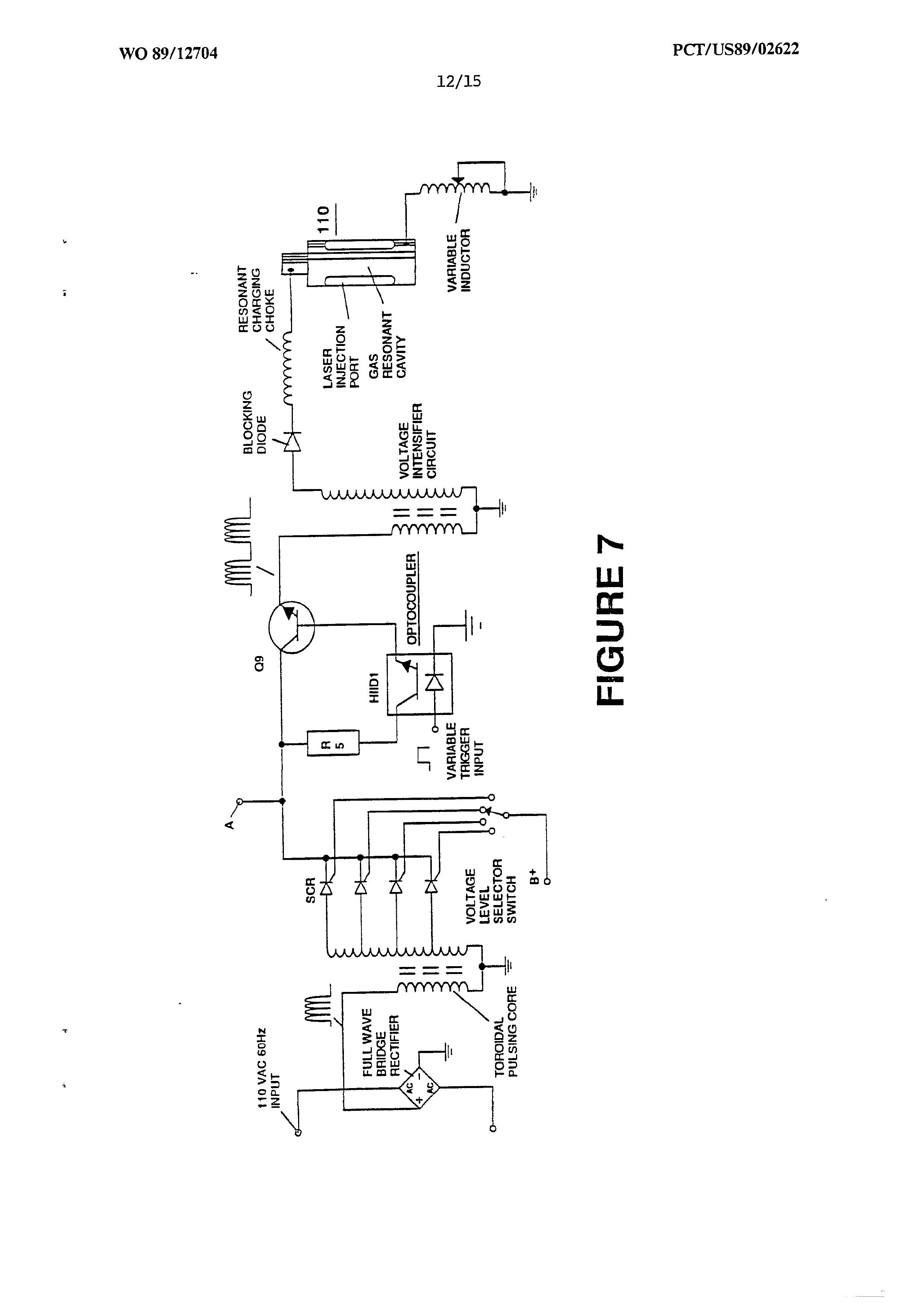
Figure 7 is an electrical schematic of the voltage source for the Zas resonant cavity.
-
circuit of the type shown in Figure 7 provides a pulsating, polar electric field to the gas mixture as illustrated in Figure 6A, whereby electrons of the gas atoms are distended in their orbital fields by reason of their subjection to el …
-
… The "extraction" of electrons by the sink means is coordinated with the pulsating electrical field of the resonant cavity produced by the circuit of Figure 7, by means of an interconnected synchronization circuit, such as shown in Figure 8B. …
-
… To cause and maintain atomic elongation depicted in Figure 6C before gas ignition, a voltage intensifier circuit such as shown in Figure 7 is utilized as a current restricting voltage source to provide the excitation voltage applied to the resonant cavity. …
-
… The incoming positive wave form applied to resonant cavity voltage zone through a blocking diode is synchronized with the pulse train applied to the gas resonant cavity by the circuit of Figure 7 via alternate gate circuit. …
-
FIGURE 7