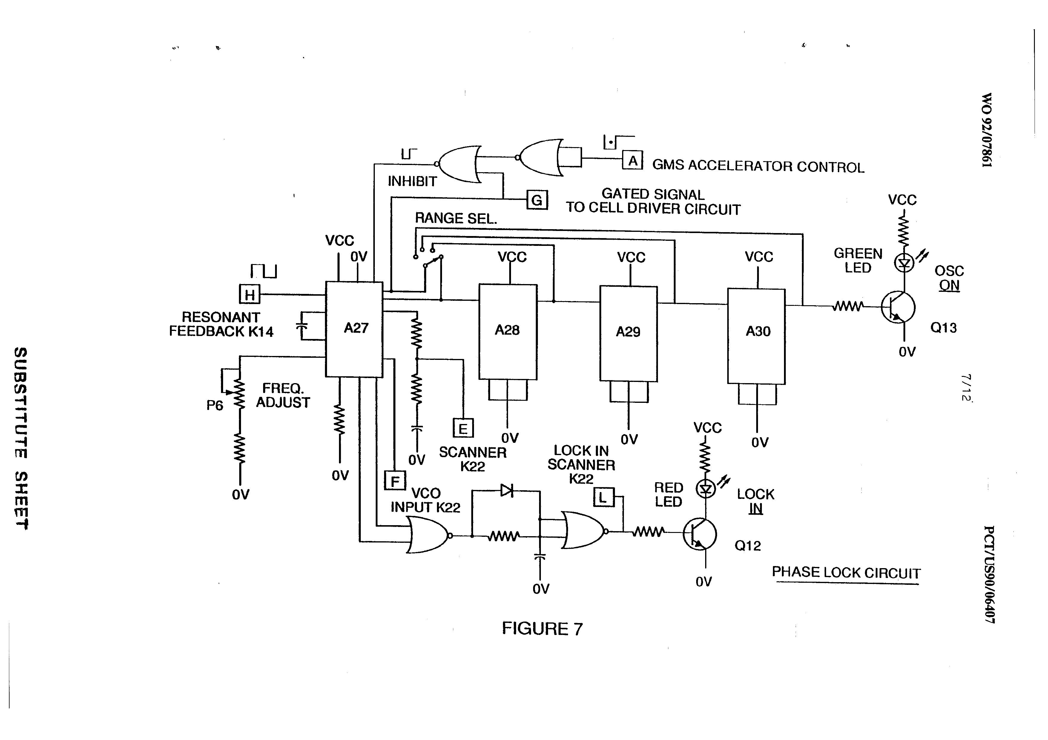
Figure (7)
Figure (7)
How it is written
- (7) 3×
Drawings 1
Where it is named · 3
A control and driver circuits for a hydrogen gas fuel producing cell 3×
-
Figure 7, a phase lock loop, allows pulse frequency to be maintained at a predetermined resonant condition sensed by the circuit. Together, the circuits of Figures 7 and 8 determine an output signal to the pulsing core until the peak voltage signal sensed at
-
FIGURE 7