
ESP32 - Complex Waveform Generator V3
Installing and Using the ESP32 Complex Waveform Generator V3 Application
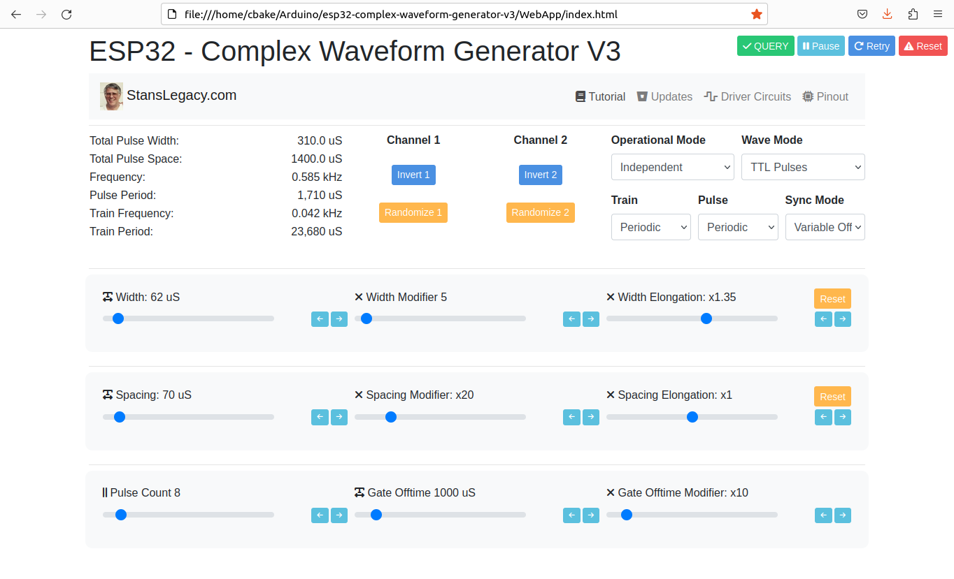
Screenshot of web interface
 |
 |
Prerequisites
To use this application, you need to have the Arduino IDE installed on your computer. You can download the Arduino IDE from the official website: https://www.arduino.cc/en/software
-
ESP32 Development Board: You'll need an ESP32 development board, such as the popular ESP32-DevKitC or ESP32-WROOM-32D. These boards typically come with Wi-Fi and Bluetooth capabilities and a variety of GPIO pins for interfacing with peripherals.
-
Rotary Encoders: To adjust the waveform parameters, you will need a total of 7 rotary encoders. You can use KY-040 rotary encoder modules or any other type of incremental rotary encoder with built-in push buttons. Ensure that the rotary encoders you choose have a CLK, DT, and SW (push button) pinout.
-
Breadboard and Jumper Wires: A breadboard and jumper wires are required to make the necessary connections between the ESP32 development board and the rotary encoders.
- Power Supply: You will need a power supply to power the ESP32 development board. This can be a USB power supply, a battery, or any other suitable power source that meets the board's voltage and current requirements, such an ATX Supply from a computer. 5VDC 1A minimum is recommended to prevent brownout conditions while interacting with a driver circuit.
-
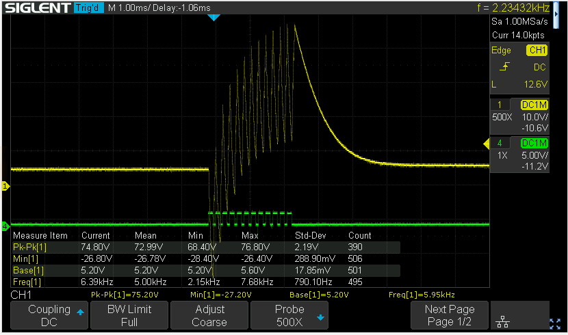
Oscilloscope (optional): To visualize the generated waveform, you can use an oscilloscope. Connect the output pins (channel1OutputPin and channel2OutputPin) from the ESP32 development board to the oscilloscope's input channels.
Installing required libraries
-
ArduinoJson: To install the ArduinoJson library, follow these steps: a. Open the Arduino IDE. b. Click on
Toolsin the menu bar, thenManage Libraries. c. In the Library Manager window, search for "ArduinoJson" in the search bar. d. Find "ArduinoJson by Benoit Blanchon" in the search results and click on theInstallbutton. -
ESP32Encoder: To install the ESP32Encoder library, follow these steps: a. Open the Arduino IDE. b. Click on
Toolsin the menu bar, thenManage Libraries. c. In the Library Manager window, search for "ESP32Encoder" in the search bar. d. Find "ESP32Encoder by Gil Mora" in the search results and click on theInstallbutton.
Uploading the Application
- Download the source code for the ESP32 Complex Waveform Generator V3 application or copy it to a new file in the Arduino IDE.
- Connect the ESP32 development board to your computer using a USB cable.
- In the Arduino IDE, select the appropriate board and port under
Tools>BoardandTools>Port. - Click on the
Uploadbutton (right-facing arrow icon) in the Arduino IDE to compile and upload the application to the ESP32 development board.
Hardware Setup
- Wire the rotary encoders and other components according to the pin assignments defined in the source code.
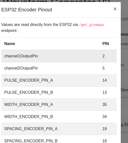
ESP32 Pin Encoder Connection Encoder Function 14 Pulse Encoder CLK Pulse count 13 Pulse Encoder DT Pulse count 35 Width Encoder CLK Pulse width 34 Width Encoder DT Pulse width 19 Spacing Encoder CLK Pulse spacing 18 Spacing Encoder DT Pulse spacing 23 Off-time Encoder CLK Off-time 22 Off-time Encoder DT Off-time 27 Width Mod Encoder CLK Width modifier 26 Width Mod Encoder DT Width modifier 15 Spacing Mod Encoder CLK Spacing modifier 32 Spacing Mod Encoder DT Spacing modifier 33 Off-time Mod Encoder CLK Off-time modifier 4 Off-time Mod Encoder DT Off-time modifier 2 Output Channel 1 Output waveform 5 Output Channel 2 Output waveform - Make sure the connections are secure and verify the CLK/DT pins for each encoder are wired correctly, and that each encoder turns in the correct direction relative to the respective parameter change.
Using the Application
- Power on the ESP32 development board.
- Use the rotary encoders to adjust the following parameters:
- Pulse count
- Pulse width
- Pulse spacing
- Off-time
- Width modifier
- Spacing modifier
- Off-time modifier
- The application will generate a complex waveform based on the adjusted parameters.
- Connect the output pins (channel1OutputPin and channel2OutputPin) to an oscilloscope to visualize the generated waveform.
- Open the WebApp/index.html page in a browser.
- Fine-tune the parameters using the rotary encoders to achieve the desired waveform shape and characteristics.
Next Steps For Utilization
- Build ESP32 CWG - VIC Driver circuit(s) - https://stanslegacy.com/books/chris-bake/page/esp32-cwg-driver-amplification
- Cell Construction - https://stanslegacy.com/books/ethan-crowder/page/resonant-cavity-related
Troubleshooting
- If the waveform does not match the expected output, verify the wiring connections and ensure the rotary encoders are functioning correctly.
- If the application does not upload to the ESP32 development board, double-check the board and port selection in the Arduino IDE.
- If the rotary encoders behave unexpectedly (e.g., adjusting one parameter affects another), check the CLK/DT pin assignments and wiring.
-
Click the PInout button to fetch the currently defined GPIO pins from the ESP32 directly and confirm they are wired correctly.

For further assistance or to report any issues, contact the application's support team or refer to the community forums.