2 Arduino - Dual Channel - Triple AND Gate (Perfect Pulse Driver)
By: Chris Bake
Arduino Code: https://bitbucket.org/cbake6807/dualtripleseq/src/master/
Parts List
- External Signal Generator: 0-5Vppk output.
- Power Supply: ATX is ideal, providing +5V REG and +12V REG.
- 2N7000 Signal MOSFETs: Quantity 6.
- IRFP460 or Similar Power N-channel MOSFET: Quantity 2.
- 56Ω 1/8W Resistors: Quantity 10.
- 100Ω 1/2W Resistors: Quantity 2.
- 4.7kΩ Resistors: Quantity 2.
- 2N3906 PNP General Purpose Transistor: Quantity 2 (can be substituted with any general PNP transistor).
- IR2110PB Gate Driver Chip 14-pin: Quantity 2.
- Arduino Nano (or similar): Quantity 2 (must support hardware PCNT).
- Rotary Encoder: Quantity 1.
Software Requirements
- Arduino IDE: Ensure it is installed and updated to the latest version.
- Encoder Library: Install via the Arduino Library Manager.
Arduino Setup
Pulse Counter Arduino
-
Upload Script
- Open the Arduino IDE.
- Connect the first Arduino (PulseCounter) to your PC.
- Open
PulseCounter.inofrom the provided file. - Upload the script to the Arduino.
-
Connect the Encoder
- Connect the encoder's VCC to the Arduino's 5V pin.
- Connect the encoder's GND to the Arduino's GND pin.
- Connect the encoder's CLK and DT pins to two digital pins on the Arduino D2 and D3.
- Connect the encoder's Button pin to D4.
-
Verify Encoder Output
- Open the Serial Monitor in the Arduino IDE.
- Rotate the encoder and check the output to confirm it is functioning correctly.
const int outputPin = 9;const int encoderPinA = 2;const int encoderPinB = 3;const int encoderSwitchPin = 4;const int disableSwitchPin = 6;
Adding a Pushbutton for Sync Mode Toggle
Parts Required
Hardware Connections
-
Connect the Pushbuttons
- NANO1 - D6 -> BUTTON -> GND
- NANO2 - D4 -> BUTTON -> GND
Summary of Connections
Sequencer Arduino
- Upload Script
- Disconnect the PulseCounter Arduino and connect the second Arduino (Sequencer) to your PC.
- Open
Sequencer.inofrom the provided file. - Upload the script to the Arduino.
Pin Mapping and Connections
Connecting the Two Arduinos
-
PulseCounter Arduino to Sequencer Arduino
- Signal Generator (+5Vppk max) →PulseCounter NANO1 - D5 (Input)
- Signal Generator (+5Vppk max)→Q2 First 2N7000 FET Gate
- Signal Generator (+5Vppk max)→Q7 First 2N7000 FET Gate (opposite branch)
- PulseCounter NANO1 - D9 (Output) → Sequencer NANO2 - D2 (Input)
- PulseCounter NANO1 - D9 (Output) → Q1 Second 2N7000 FET Gate
- PulseCounter NANO1 - D9 (Output) → Q6 Second 2N7000 FET Gate (opposite branch)
- Signal Generator (+5Vppk max) →PulseCounter NANO1 - D5 (Input)
-
Sequencer Arduino Outputs
- Sequencer NANO2- D9 (Output) → Input to Q4 - Third 2N7000 Gate.
- Sequencer NANO2 - D10 (Output) → Input to Q9 - Third 2N7000 Gate (opposite branch)
- Gate Enable/Disable Button
- Connect NANO1 - D6 -> BUTTON -> GND
- SyncMode / Offset Mode Button
- Connect NANO2 - D4 -> BUTTON -> GND
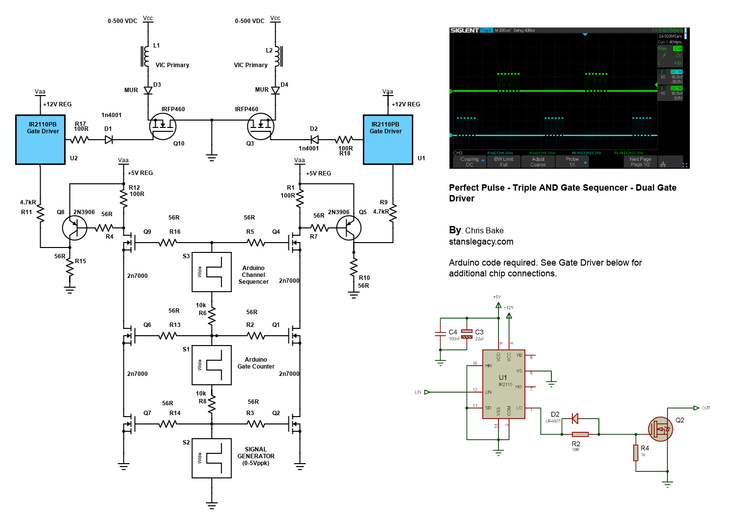
Note: The schematic shows the outputs merged due to limitations, but there should be dual outputs from the sequencer, D9 and D10, each connecting to a separate AND gate tree.
Gate Driver Chip Connections
IR2110PB Gate Driver Chip
-
Power Connections
- VCC (Pin 3) → +12V REG
- VSS (Pin 2, 10, 11, 15) → GND
- VDD (Pin 9) +5V REG
-
Input Connections
- LIN (Pin 12) → Arduino PWM pin (as per script)
-
Output Connections
- LO (Pin 1) → Gate of the IRFP460 MOSFET
-
Bootstrap Capacitor
- Connect a 22µF and a 100nF capacitor near VDD (Pin 9) and Ground.
- No Connection
- Pin 6, 7 - NC
-
Noise Filtering
- R2: Connect a 10Ω resistor between LO and the gate of the MOSFET.
- D2: Place a 1N4001 diode in parallel with the Resistor R2 in reverse direction for added noise filtering and protection.
Schematic Overview
Refer to the schematic image to visualize these connections. The IR2110PB gate driver chips control the IRFP460 MOSFETs, enabling high-power switching of the VIC (Voltage Intensifier Circuit) primaries.
Additional Notes
- Resistor Tolerances: The resistors can have a large tolerance. The 56Ω value is selected to preserve signal clarity. Any value ≤220Ω should be acceptable.
- Merged Outputs: The Arduino Channel Sequencer has 2 outputs shown merged due to Scheme-It limitations.