
ENERGY of the FUTURE - R&Z - Vol 2 No. 1, 1990
WATER FUEL CELL Quenching Circuit Technology on how to Render Hydrogen Safer than Natural Gas
by Stanley A. Meyer, 3792 Broadway, Grove City, Ohio 43123
Copyright © 1981 By Stanely A. Meyer
© under UCC 1987 By Stanley A. Meyer
|
Interview: Cell now ready for existing cars There was an urgency in Stan Meyer's voice, booming into the raum&zeit office on Sept. 7, 1990. Chrystyne Jackson had switched on the intercom and Jeane Manning took notes. "We're finalizing pre-engineering of the (hydrogen-powered) car... to head off the Mideast crisis, Meyer said. If a war starts and chemical weapons are used, he added, oil from the Mideast could be contaminated. Pressure in oil wells internationally is dropping, so even without a war, "we have less than 15 years' supply of oil coming out of the Mideast." The economic base of the world would collapse quickly, if no new source of fuel replaces oil, he added. Therefore a massive international program-similar to the Manhattan Project in level of priority accorded it is needed to develop a hydrogen-based economy. Meyer referred to the Swiss Association for Free Energy conference last year, where he was a guest speaker. When he listened to scientists there talk about alternative energy possibilities, he was shocked. There was apparently no systems engineering approach, other than his water fuel cell. The final patent for his water fuel cell technology - the patent on the electrical polarization process-has now been completed. Pre-engineering is "85 percent finalized", and he planned to run his dune buggy powered by the water fuel cell in the November 1990 solar race in Australia. His technology is to be unveiled to representatives of 176 nations this fall in Sweden. Much information needs to be communicated. Most people think of hydrogen as a volatile fuel. However, Meyer's process "renders hydrogen safer than natural gas". Following is a memo from Stanley A. Meyer (of Grove City, Ohio), describing his Quenching Circuit Technology, He explains that this technology breakthrough allows the water fuel cell technology to be retrofitted to an existing engine without engine change! |
Quenching Circuit TechnologyThe quenching circuit technology is an combination and integration of several Gas-Processes that uses noncombustible gases to render hydrogen safer than natural gas. The "Non-Burnable" gases are used to adjust hydrogen "Burn-Rate" to Fuel- Gas burning levels... recycled to stabilize Gas-Flame temperatures... inter- mixed to sustain and maintain a hydrogen Gas-Flame... and used to prevent Spark-Ignition of supply gases, The utilization and recycling of the non-combustible gases allows the Water Fuel Cell to become a Retrofit Energy System. The Quenching Circuit Technology is systematically activated and performed In the following way. Data Reference: WFC Tech-Brief Method: Using Non Combustible Gases to render Hydrogen safer than Natural Gas Operational ParametersSpark Ignition Tube Spark-Ignition Tube (b) is a tubular test apparatus (1/8 diameter) that deter mines and measures the "Bum-Rate" of different types of Burnable Gases intermixed with Ambient Air, as illustrated in Figure 1.1 |
Water Fuel Cell
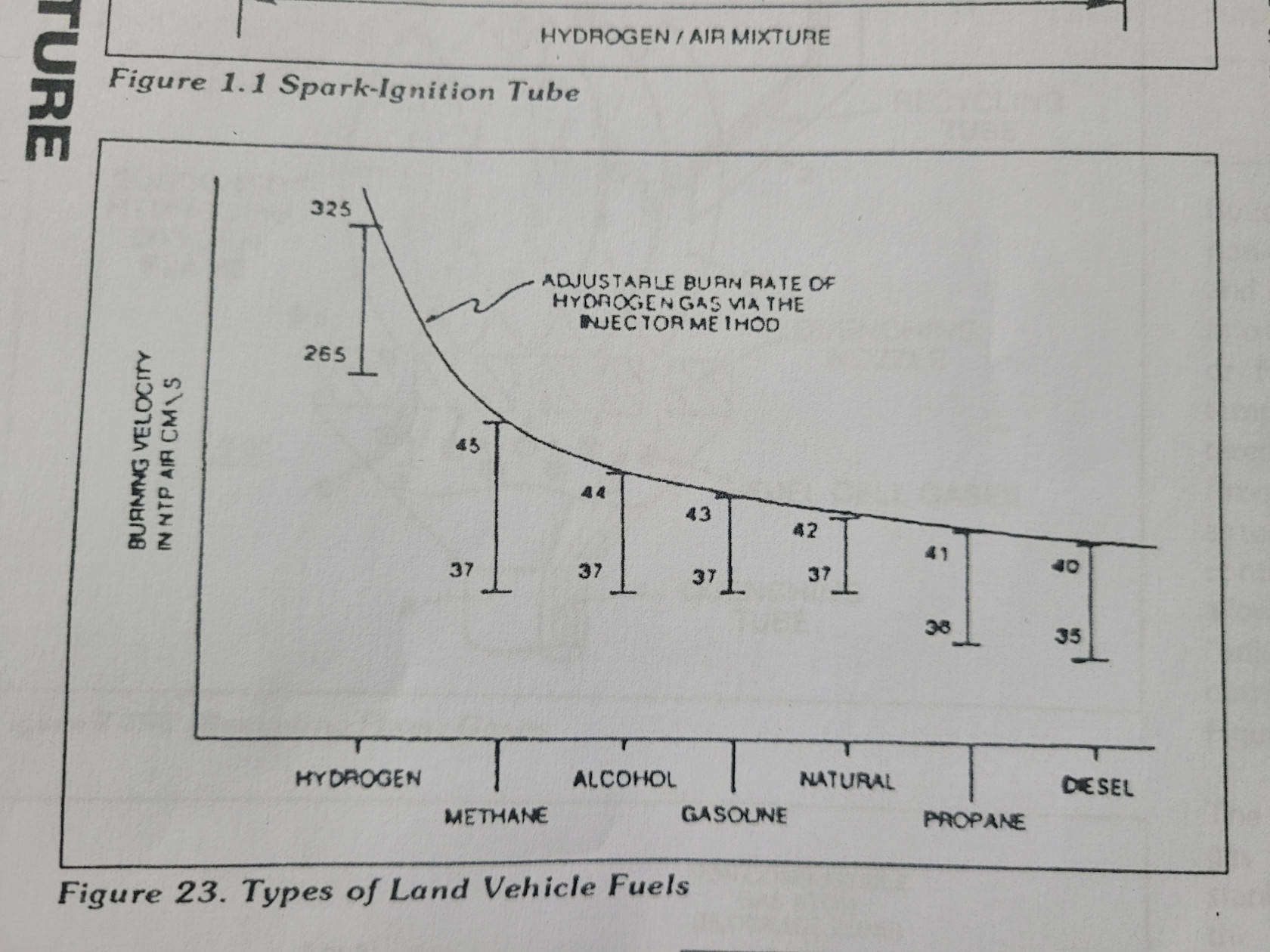
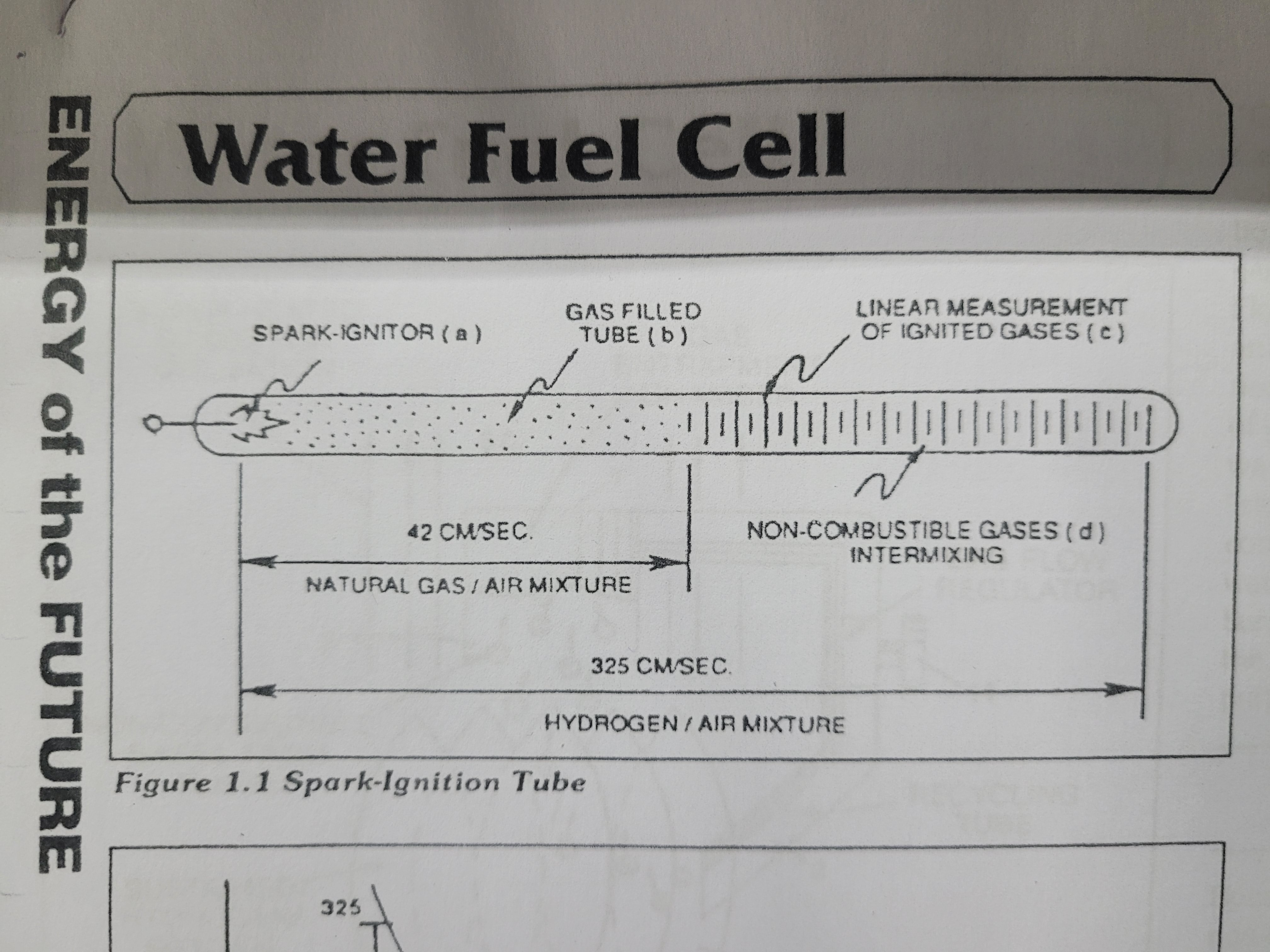 Spark-Ignitor (a) causes and starts the Burnable Gas Mixture (b) to undergo Gas-Ignition which, in turns, supports and allows Gas Combustion to take place...forming and sustaining a Gas- Flame. The expanding and moving Gas-Flame travels (away from spark-ignitor) the linear length of the gas filled tube (c) and is "detected" and "measured (length between spark-ignitor and light-detector) in one second after gas-Ignition, The Gas-Ignition Process, now, establishes the "Burn-Rate" of a Burnable Gas Mixture in centimeters per second (cm/sec.), as illustrated in Figure 23.
Different types of "Burnable" Gas-Mixtures exposed to the Gas-Ignition Process were tested, measured, recorded and systematically arranged as to cm/ sec. length, see vertical bar Graph 23 again The Gas-Ignition Process was performed several times to establish the "average" Burn-Rate of the Fuel- Gases which, in turn, establishes the length of the vertical bars.
Figure 1.1 Spark-Ignition Tube
 Gas Injection Process

Injecting and Intermixing an Non- Combustible Gas (d) (non-burnable gas) with the "Burnable Gas-Mixture (b) "changes" or "alters" the gas-mixture "Burn-Rate". Increasing the volume-amount of Non-Combustible Gas (d) diminishes and/or lowers the "Bum- Rate" of the Gas Mixture (b/d) still further. Progressive and controlled intermixing of the non-combustible gases (b/d) allowed the "Burn Rate of Hydrogen to be "lowered" or "adjusted" to "match" or "co-equal" the "Burn-Rate" of other Fuel-Gases, see curve line in Figure 23.
Figure 23. Types of Land Vehicle Fuels
In terms of operational performance, the Non-Combustible gas (d) does "Not support the Gas Combustion Process: since the Non Burnable Gas (d) "restricts or "retards the speed at which the Oxygen Atom unites with Hydrogen Atoms to cause Gas Combustion. The "Gas Retarding Process" is, of course, applicable to any type or combination of Burnable Gases or Burnable gas mixture.
Figure 24. Rendering Hydrogen Safer than Natural Gas
 Gas Mixing Regulator
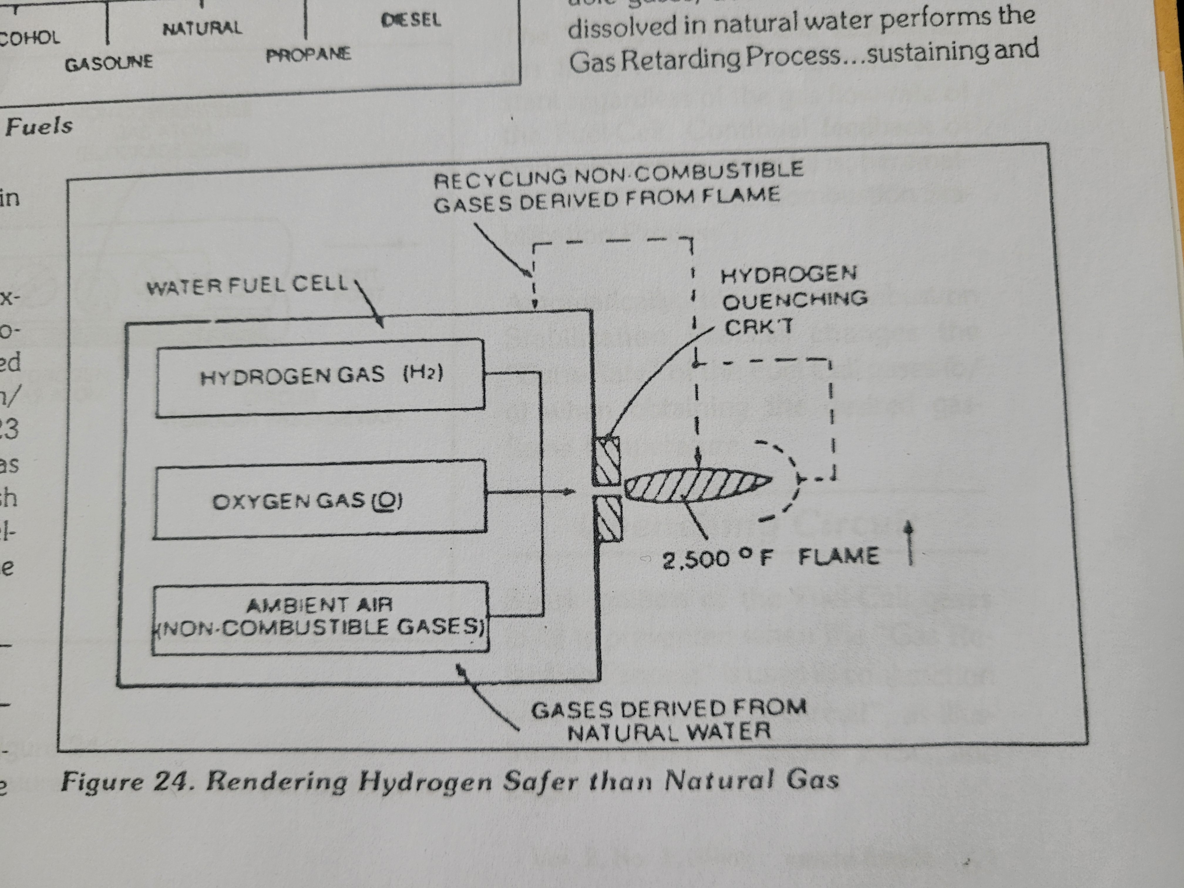
Inherently, the WATER FUEL CELL allows the "Burn-Rate of Hydrogen to be changed" or "adjusted" from 325cm/sec. to 42cm/sec. (Co-equal- ling Natural Gas burning levels) since Non-Combustible Gases (such as Nitrogen, Argon, and other non-burn- able gases) derived from Ambient Air dissolved in natural water performs the Gas Retarding Process... sustaining and maintaining an Open-Air Flame beyond 5,000 degrees F, as illustrated in Figure 24.
Natural water acts and performs as an "Gas Mixing Regulator" when the Fuel Cell is electrically energized by way of voltage stimulation (Electrical Polarization Process) producing an uniform gas-mixture (b/d) regardless of the Gas Flow-Rate of the Fuel-Cell... producing an uniform gas-mixture (b/d) only when needed. In quiescent-state, the supply of gases (b/d) being released from the water bath is "terminated" and "stopped when the Fuel Cell becomes "de-energized".
The unused water, of course, remains as an non- burnable liquid. The gases (b/d) above the water bath is "vented" for safety purposes.
 Flame-Temperature Adjustment
By capturing and recycling the expelled non-combustible gases (d) (derived from and supplied by the water bath) back into the sustained hydrogen gas-flame or Fuel-Cell causes the gas flame temperature to be "changed" or "altered" by way of the Gas Retarding Process, as illustrated in Figure 24SC as to Figure 24. The recycling gases (d) controlled by an Gas Flow Regulator allows the gas flame-temperature to be "adjusted" or "calibrated" to any gas burning level (s), as so illustrated in Figure 23.
The "newly formed and established gas flame-temperature remains constant regardless of the gas flow-rate of the Fuel Cell. Continual feedback of non-combustible gases (d) is, hereinafter, called The Gas Combustion Stabilization Process". Automatically, the Gas Combustion Stabilization Process changes the "Burn-Rate" of the Fuel Cell gases (b/d) when obtaining the desired gas. flame temperature.
Figure 24SD. Preventing Gas Ignition
 Quenching Circuit
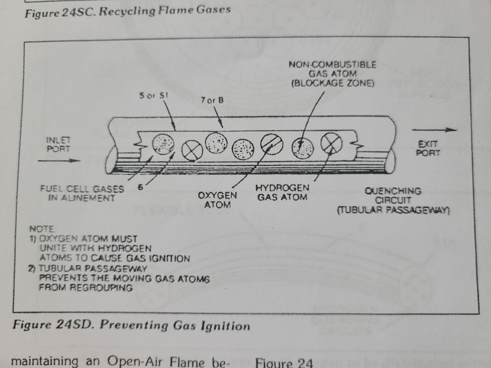
Spark-Ignition of the Fuel-Cell gases (b/d) is prevented when the "Gas Retarding Process" is used in conjunction with an "Quenching Circuit", as illustrated in Figure 24, 24SB, 245C, and 24SD.
The non-combustible gases (d) separates and prevents the hydrogen atoms to unite with oxygen atoms to "bring-on" or "initiate" Gas-Ignition. The narrow passaway (at least 1/8 inch long and having an .015 diameter) prevents the moving gas atoms from "Re-Grouping".
The alignment of the Fuel Cell gases (b/d) inside the tubular-passaway is, hereinafter, called "The Quenching Circuit" The Quenching Circuit "Anti- Spark technique" is "Independent" of Gas-Velocity.
Figure 245A. Catalytic Block Asss'y
 Quenching Nozzle
Additional Quenching Circuits arranged In an Disc-shape configuration forms an "Quenching Nozzle" when attached to an "Quenching Tube", as illustrated In Figure 24SC as to Figure 245B, The Multi Gas-Port Disc compensates for increased Gas-Velocity while "preventing" spark-Ignition of the Fuel-Cell gases. The overlapping Flame-Pattern re-ignites the expelling hydrogen gas mixture (b/d) should Flame out occur. Ceramic material is used to form the "Quenching Disc" to "prevent" hale- size enlargement due to gas-oxidation.
The non-combustible gases (d) keeps the Ceramic Material "cool-to-the- touch by projecting the Gas-Flame beyond and away from the disc- surface...the Quenching Disc remains "cool" even if the Gas-Flame Temperature exceeds the melting-point of the disc-material.
 Quenching Tube
The Quenching Disc is extended into an Flexible Tube to transport the Fuel- Cell gases safely over long distances, as illustrated in Figure 25. The Spark- Arresting Gas-line is, hereinafter, called "The Quenching Tube".
Figure 25. Quenching Tube allows the Hydrogen to be distributed without Spark-Ignition
Catalytic Block Assembly
An inverted hemispherical cavity placed on top of and in space relationship to the "Quenching Disc" insures total gas- combustion by recycling any "escaped" or "unused burnable gases back into the gas-flame for Gas-Ignition... preventing Gas-Oxide formation, as illustrated in Figure 24SA as to Figure 24SC.
Internal Combustion Engine
The Gas Combustion Stabilization Process (recycling non-combustible gases) is also applicable to operating an Internal Combustion Engine without changing Engine Parts since the Gas Retarding Process allows the hydrogen "Burn-Rate" to "equal" the "Burn-Rate" of Gasoline or Diesel-Fuel, as illustrated in Figure 23. The engine pro
Vol 2. No 1, 1990 raum&zelt