
ENERGY of the FUTURE - R&Z - Vol 1 No. 6, 1990
Energy of the Future
Raum & Zeit Vol 1. No. 6. 1990
R&Z HFP_Page1.pdf , R&Z HFP_Page10.pdf , R&Z HFP_Page2.pdf , R&Z HFP_Page3.pdf , R&Z HFP_Page5.pdf , R&Z HFP_Page4.pdf , R&Z HFP_Page7.pdf , R&Z HFP_Page6.pdf , R&Z HFP_Page8.pdf , R&Z HFP_Page9.pdf
Hydrogen Fracturing Process
Copyright 1983 in U.S.A. by Stanley A. Meyer under 1987 by Stanley A. Meyer
Over the years man has used water in many ways to make his life on Earth more productive. Why not, now, use water as fuel to power our cars, heat our homes, fly our planes or propel spaceships beyond our galaxy? Biblical prophecy foretells this event. After all, the energy contained in a gallon of water exceeds 2.5 million barrels of oil when equated in terms of atomic energy. Water, of course, is free and abundant. The Hydrogen Fracturing Process dissociates the water molecule by way of voltage stimulation, ionizes the combustible gases by light exposure and, then, prevents the formation of the water molecule during thermal gas ignition...releasing thermal explosive energy beyond "normal" gas burning levels under controlled state.
Circuit Component Interaction:
Pulsing Transformer
The pulsing transformer (a/g) steps up voltage amplitude or voltage potential during pulsing operations. The primary coil is electrically isolated (no electrical connection between primary and secondary coil) to form Voltage Intensifier Circuit (AA). Voltage amplitude or voltage potential is increased when secondary coil (a) is wrapped with more turns of wire. Isolated electrical ground (j) prevents electron flow from input circuit ground.
Blocking Diode
Blocking diode (b) prevents electrical "shorting" to secondary coil (a) during pulse-off time since the diode "only" conducts electrical energy in the direction of the schematic arrow.
LC Circuit
Resonant Charging Choke (c) in series with Excitor-Array (E1/E2) forms an inductor-capacitor circuit (LC) since the Excitor-Array (ER) acts or performs as a capacitor during pulsing operations. The dielectric properties (insulator to the flow of amps) of natural water (dielectric constant being 78.54 @ 25c) between the electrical plates E1/E2) forms the capacitor (ER). Water now becomes part of the VIC in the form of "resistance" between electrical ground and pulse-frequency positive-potential...helping to prevent electron flow within the pulsing circuit (AA) of Figure 1-1.
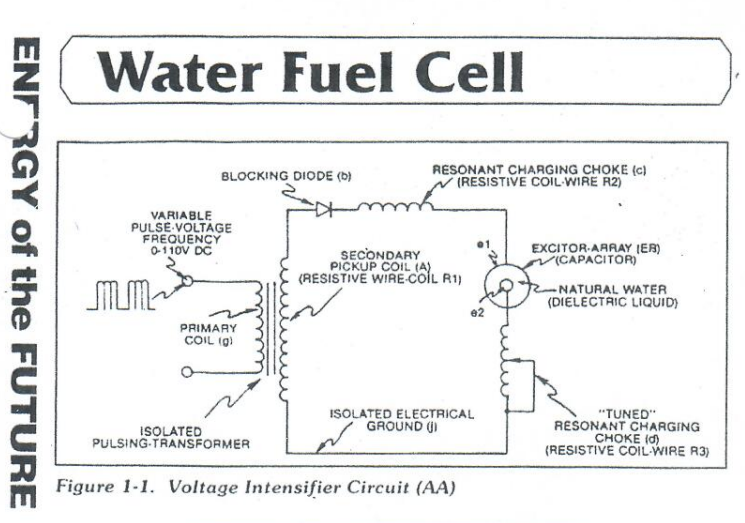
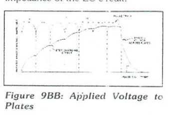
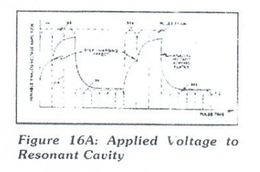
The inductor (c) takes on or becomes a Modulator Inductor which steps up an oscillation of a give charging frequency with the effective capacitance of a pulse-forming network in order to charge the voltage zones (E1/E2) to a higher potential beyond applied voltage input. The inductance (c) and Capacitance (ER) properties of the LC circuit is therefore "tuned" to resonance at a certain frequency. The Resonant Frequency can be raised or lowered by changing the inductance and/or the capacitance values. The established resonant frequency is, of course, independent of voltage amplitude, as illustrated in Figure 9BB as to Figure 16A.
The value of the Inductor (C), the value of the capacitor (ER), and the pulse-frequency of the voltage being applied across the LC circuit determines the impedance of the LC circuit.
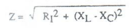
The impedance of an inductor and a capacitor in series, Z is given by:
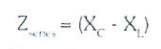
Where:
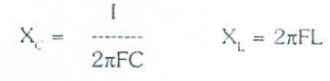
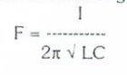
The Resonant Frequency (F) of an LC circuit in series is given by:
Ohm's law for LC circuit in series is given by:

LC Voltage
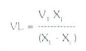
The voltage across the inductor (c) on capacitor (ER) is greater than the applied voltage (h). At frequency close to resonance, the voltage across the individual components is higher than the applied voltage (h), and, at resonant frequency, the voltage Vt across both the inductor and the capacitor are theoretically infinite. However, physical constraints of components and circuit interaction prevent the voltage from reaching infinity. The voltage (Vl) across the inductor (C) is given by the equation:
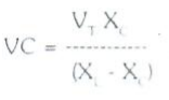
The voltage (Vc) across the capacitor is given by:
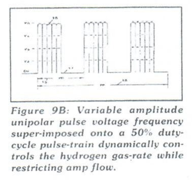
During resonant interaction, the incoming unipolar pulse-train (h) of Figure (1-1) as to Figure (9B) produces a step-charging voltage-effect across Excitor-Array (ER), as illustrated in Figure (9BB) and Figure 16A. Voltage intensity increased from zero "ground-state" to a high positive voltage potential in a progressive function. Once the voltage-pulse is terminated or switched-off, voltage potential returns to "ground-state" or near ground-state to start the voltage deflection process over again. Voltage intensity of level across Excitor-Array (ER) can exceed 20,000 volts due to circuit (AA) interaction and is directly related to pulse-train (h) variable amplitude input.
RLC Circuit
Inductor (C) is made of or composed of resistive wire (R2) to further restrict D.C. current flow beyond inductance reaction (XL), and is given by:
Dual Inline RLC Network
Variable inductor-coil (d), similar to inductor (C) connected to opposite polarity voltage zone (E2) further inhibits electron movement or deflection within the VIC. Moveable wiper arm fine "tunes" "Resonant Action" during pulsing operations. Inductor (d) in relationship to inductor (C) electrically balances the opposite voltage electrical potential across voltage zone (E1/E2).
VIC Resistance
Since pickup coil (A) is composed of or made of resistive wire-coil (R1), then total circuit resistance is given by:
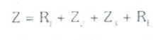
Where, Re, is the dielectric of natural water
Ohm's law as to applied electrical power, which is: E = I*R
Where P = E*I
Electrical power (P) is linear relationship between two variables, voltage (E) and amps (I).
Voltage Dynamic
Voltage is "electrical pressure" or "electrical force" within an electrical circuit and is known as "voltage potential". The higher the voltage potential, the greater "electrical attraction force" or "electrical repelling force" is applied to the electrical circuit. Voltage potential is an "unaltered" or "unchanged" energy-state when "electron movement" or "electron deflection" is prevented or restricted within the electrical circuit.
Voltage Performs Work
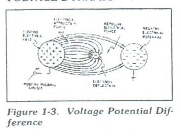
Unlike voltage charges within an electrical circuit set up an "electrical attraction force" whereas, like electrical charges within the same electrical circuit encourages a "repelling action". In both cases, electrical charge deflection or movement is directly related to applied voltage. These electrical "forces" are known as "voltage fields" and can exhibit either a positive or negative electrical charge.
Likewise, ions or particles within the electrical circuit having unlike electrical charges are attracted to each other. Ions or particles mass having the same or like electrical charges will move away from one another, as illustrated in Figure 1-3.
Furthermore, electrical charged ions or particles can move toward stationary voltage fields of opposite polarity, and, is given by Newton's second law:
A = F / M
Where the acceleration (A) or a particle mass (M) acted on by a net force (F). Net force (F) is the "electron attraction force" between opposite electrically charged entities, and, is given by Coulomb's Law:

Difference of potential between two charges is measured by the work necessary to bring the charges together, and is given by:
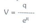
The potential at a point due to a charge (q) at a distance (R) in a medium whose dielectric constant (e).
Atomic Interaction To Voltage Stimulation
Atomic structure of an atom exhibits two types of electrical charged mass-entities, orbital electrons having negative electrical charges (-) and a nucleus composed of electrons and protons having positive charges (+). In stable electrical state, the number of negative electrically charged electrons equal the same number of positive electrically charged protons...forming an atom having "no" net electrical charge.
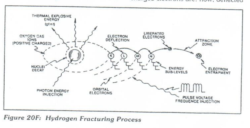
Whenever on or more electrons are "dislodged" from the atom, the atom takes on a net positive electrical charge and is called a positive ion. If an electron combines with a stable or normal atom, the atom has a net negative charge and is called a negative ion. Voltage potential within an electrical circuit (see VIC as to Figure 1-1) can cause one or more electrons to be dislodged from the atom due to opposite polarity attraction between unlike charged entities, as shown in Figure 20F (see Figure 1-3 again as to Figure 1-5) as to Newton's and Coulomb's Laws of electrical force (RR).
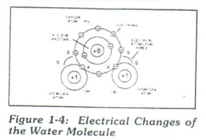
The resultant electrical attraction force (qq') combines or joins unlike atoms together by way of covalent bonding to form molecules of gases, solids, or liquids. When the unlike oxygen atom combines with two hydrogen atoms to form the water molecule by accepting the hydrogen electrons (aa' of Figure 1-4), the oxygen atoms become "net" negative electrically charged (-) since the restructured oxygen atom occupies 10 negative negatively electrically charged electrons as to only 8 positive electrically charged protons. The hydrogen atom with only its positive charged proton remaining and unused, now, takes on a "net" positive electrical charge equal to the electrical intensity of the negative charges of the two electrons (aa') being shared by the oxygen atom...satisfying the law of physics that for every action there is an equal and opposite reaction. The sum total of the two positive charged hydrogen atoms (++) equaling the negative charged oxygen atoms forms a "no" net electrical charge molecule of water. Only the unlike atoms of the water molecule exhibits opposite electrical charges.
Voltage Dissociation of the Water Molecule
Placement of a pulse-voltage potential across the Excitor_Array (ER) while inhibiting or preventing electron from within the VIC (AA) causes the water molecule to separate into its component parts by momentarily, pulling away orbital electrons from the water molecule, as illustrated in Figure 1-5.
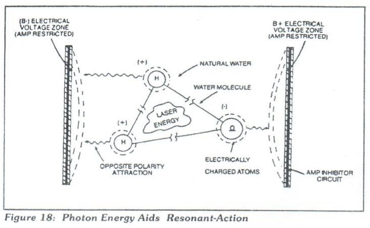
The stationary "positive" electrical voltage-field (E1) not only attracts the negative charged oxygen atom but also pulls away negative charged electrons from the water molecule. At the same time, the stationary "negative" electrical voltage field (E2) attracts the positive charged hydrogen atoms. Once the negative electrically charged electrons are dislodged from the water molecule, covalent bonding (sharing electrons) ceases to exist, switching off or disrupting the electrical attraction forces (qq') between the water molecule atoms. Dissociation of the water molecule by way of voltage stimulation is herein called "The Electrical Polarization Process".
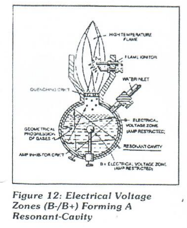
Subjecting or exposing the water molecule to even higher voltage levels causes the liberated atoms to go into a "state" of gas ionization. Each liberated atom taking on its own "net" electrical charge. The ionized atoms along with free floating negative charged electrons are, now, deflected (pulsing electrical voltage fields of opposite polarity) through the Electrical Polarization Process...imparting or superimposing a second physical force (particle-impact_ unto the electrically charged water bath. Oscillation (back and forth movement) of an electrically charged particle by way of voltage deflection is hereinafter called "Resonant Action", as illustrated in Figure 12.
Attenuating and adjusting the "pulse-voltage amplitude" with respect to the "pulse voltage frequency" now, produces hydrogen gas on demand while restricting amp flow.
Laster Interaction
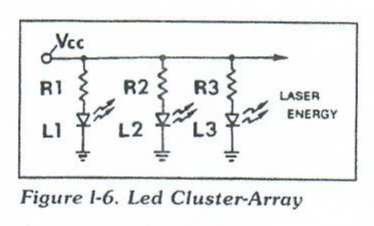
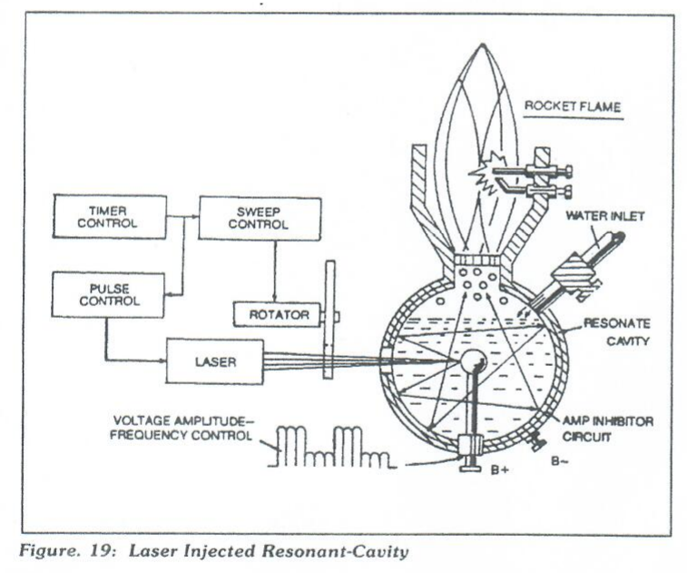
Light Emitting Diodes (LEDs) arranged in a cluster array provides and emits a narrow bank of visible light energy into the voltage stimulated water bath, as illustrated in Figure 19 as to Figure 18. The absorbed laser energy (electromagnetic energy) causes many atoms to lose electrons while highly energizing the liberated combustible gas ions prior to an during thermal gas-ignition. Laser or light is linear with respect to the forward current through the LEDs, and, is determined by
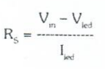
Where I(led) is the specified forward current (typically 20mA, per diode); V(led) is the LED voltage drop (typically 1.7 volts for red emitters). Ohm's Law for LED circuit in parallel array, and, is given by:

Where I is the forward current through LED cluster-array; Vcc is the volts applied (typically 5 volts). Whereby, laser or light intensity is variable as to duty cycle on/off pulse-frequency from 1Hz to 65Hz and above is given by:
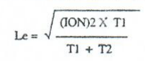
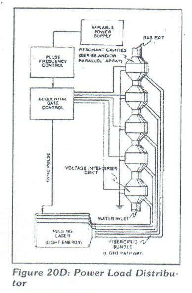
Le is light intensity in watts: T1 is current on time; T2 is current off time; and (ION) = RMS value of load current during on period. Injecting laser energy into the Electrical Polarization Process and controlling the intensity of the light-energy causes the combustible gases to reach a higher energy-state (electromagnetically priming the combustible gas ions) which, in turn, accelerates gas production while raising gas-flame temperatures beyond "normal" gas-burning levels. Injecting "Electromagnetically Primed" and "Electrically Charged" combustible gas ions (from water) into other light-activated Resonant Cavities further promotes gas-yield beyond voltage/laser stimulation, as illustrated in Figure 20D as to Figure 20.
Electron Extraction Process
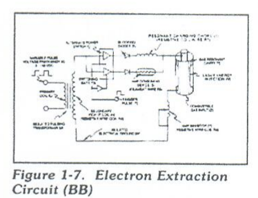
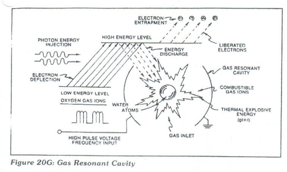
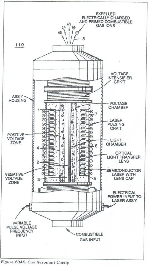
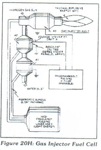
Exposing the displaced and moving combustible gas atoms (exiting water-bath and passing through Gas Resonant Cavity (T), Figure 20JX as to Figure 20H to another or separate pulsing laser energy-source (V) at higher voltage levels (E3/E4) causes more electrons to be "pulled away" or "dislodged" from the gas atoms, as illustrated in Figure 1-8 as to Figure 20F. The absorbed laser energy "forces" or "deflects" the electrons away from the gas atom nucleus during voltage-pulse off time. The recurring positive voltage-pulse (k) attracts (qq') the liberated negative electrically charged electrons to positive voltage zone (E3). While, at the same time, the pulsating negative electrical voltage potential (E4) attracts (qq') the positive electrical charged nucleus. The positive electrical voltage field (E3) and negative electrical voltage field (E4) are triggered SIMULTANEOUSLY during the same duty-pulse. Electron Extraction Circuit (BB) of Figure 1-7 removes, captures, and consumes the "dislodged" electrons (from gas atoms) to cause the gas atoms to go into and reach "Critical State", forming highly energized combustible gas atoms having missing electrons. Resistive values (R4, R6, R7 and dielectric constant of gas Rg) and isolated electrical ground (W) prevents "electron flow" or "electron deflection" from occurring within circuit (BB) during pulsing operations (at resonant frequency) and, therefore, keeps the gas atoms in critical-state by "NOT" allowing electron replacement to occur or take place between the moving gas atoms. The "dislodged" negative charged electrons are "destroyed" or "consumed' in the form of "heat" when Amp Consuming Device (S) (such as a light bulb) is positive electrically energized during alternate pulsing operations. Laser activated or laser primed gas ions repels or "dislodged" electrons being consumed, as illustrated in Figure 20F as to Figure 20G. The Electron Extraction Process (BB) is, hereinafter, called "The Hydrogen Gas Gun" and is placed on top of a Resonant Cavity Assembly, as illustrated in Figure 20JX as to Figure 20H.
Thermal Explosive Energy
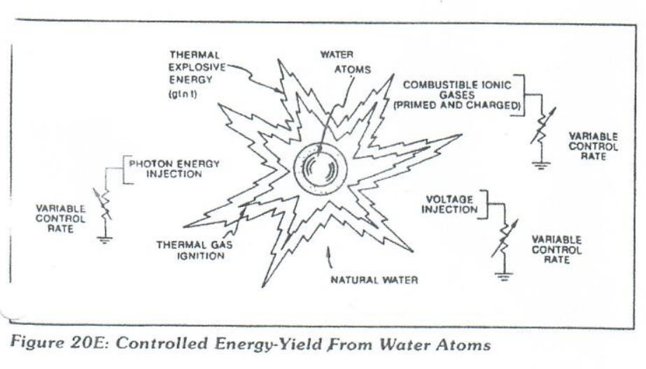
Exposing the expelling "laser-primed" and "electrically charged" combustible gas ions (exiting from Gas Resonant Cavity) to a thermal-spark or heat-zone causes thermal gas-ignition, releasing thermal explosive energy (gtnt) beyond the gas-flame stage, as illustrated in Figure 20E as to 20H.
Thermal atomic interaction (gtnt) is caused when the combustible gas ions (from water) fail to unite or form a covalent link up or covalent bond between the water molecule atoms, as illustrated in Figure 1-9.
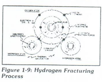
The oxygen atom having less than four covalent electrons (Electron Extraction Process) is unable to reach "stable-state" (six to eight covalent electrons required) when the two hydrogen atoms seek to form the water molecule during thermal gas ignition. The absorbed laser energy (Va, Vb, and Vc) weakens the "electrical bond" between the orbital electrons and the nucleus of the atoms. And, electrical attraction-force (qq'). Being stronger than "normal" due to the lack of covalent electrons, "Locks Onto" and "Keeps" the hydrogen electrons. This Atomic Thermal-Interaction between combustible gas ions is now called "The Hydrogen Fracturing Process". By simply attenuating or varying voltage amplitude in direct relationship to voltage pulse-rate determines Atomic Power-Yield under control-state.
Rocket Propulsion
Add-on resonant cavities (placed beneath the Hydrogen Gas Gun Assembly) arranged in parallel to vertical cluster-array increases the atomic energy-yield of the Hydrogen Fracturing Process undergoing thermal gas-ignition, as illustrated in Figure 17 as to Figure 20. This cluster-assembly or cluster-form is, hereinafter, called "the water power rocket engine".
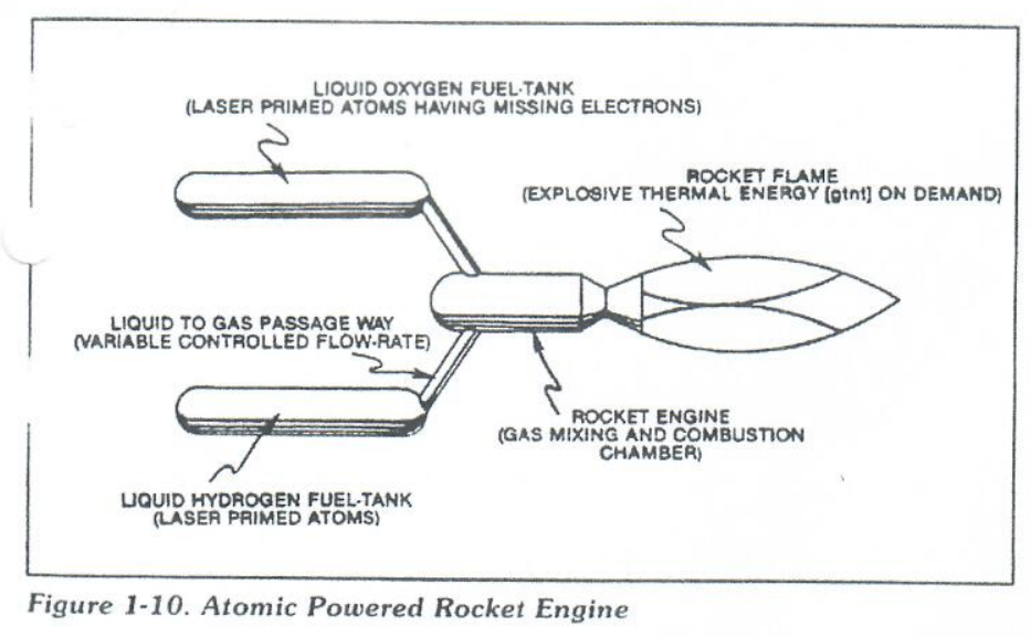
Prolong-rocket-flight carrying heavier payloads is achieved by liquifying the "specially treated" combustible gas ions (laser primed oxygen gas atoms having missing electrons and laser primed hydrogen gas atoms) under pressure in separate fuel tasks affixed to a Rocket Engine, as illustrated in Figure 1-10. Rocket thrust is now, controlled by the flow rate of the combustible ion gases entering the combusting chamber of the rocket engine once gas-ignition occurs.
In Summation
The Hydrogen Fracturing Process simply triggers and releases atomic energy from natural water by allowing highly energized sub-critical combustible gas ions to come together during thermal gas ignition. The Voltage Intensifier Circuit brings on the "Electrical Polarization Process" that switches off the covalent bond of the water molecule without consuming amps. The Extraction Circuit not only decreases the mass size of the combustible gas atoms, but, also and at the same time produces "electrical energy" when the liberated electrons are directed away from the Hydrogen Gas Gun Assembly. The Hydrogen Fracturing Process has the capability of releasing thermal explosive energy up to and beyond 2.5 million barrels of oil per gallon of water under control state...which simply prevents the formation of the water molecule during thermal gas ignition...releasing thermal explosive energy beyond the normal gas combustion process. The Hydrogen Fracturing Process is environmentally safe. The Hydrogen Fracturing Process is design variable to retrofit to any type of energy consuming devise since the Hydrogen Gas Gun can be reduced to the size of an auto spark plug or a gas injector port of a fighter aircraft or enlarged to form a rocket engine. Prototyping determines operational parameters. The Hydrogen Fracturing Process is registered under and certified under the patent cooperation treaty act via foreign grant license #492680 issued July 10, 1989 and foreign grant license #490606 issued Nov. 15, 1988 by the USA as a U.S. patent #4,826,581 issued May 2, 1989. other PCT patent application are pending allowances worldwide.