

patent · US3987783A
Solar heating panel
26 October 1976
Text
Page 1bibliographic recordscan →
United States Patent (19)
Powell
(54) SOLAR HEATING PANEL
inventor: Hayward Powell, 3180 Carlin Ave.,
Lynwood, Calif. 90262
(51 Int. Cl.............................................. F24J 3/02
UNITED STATES PATENTS
1,068,650 7/1912 Harrison............................. 126/271 1,250,260 1 2/1917 Wilcox.... ... 126/271 2,167,576 7|1939 Kiser....... - -- - --- -- - --- - - 126/271
2,213,894 9/1940 Barry.................................. 126/271 2,31 1579 2/1943 Scott................................... 126/27 | 2,993, 125 7/1961 Geer et al....................... 126/271 X 3, 174,915 3/1965 Edlin................................... 126/271
3,279,527 10/1966 Hardy................................. 126/271 3,595,216 7/1971 Lanciault............................ 126/271
Primary Examiner-Kenneth W. Sprague
Attorney, Agent, or Firm-Harris, Kern, Wallen &
Tinsley
A solar heating panel with a heat collector mounted on an insulating base and an arched cover over said collector mounted in clips at the edges of the base.
One or two flexible covers slidingly positioned in channels of the mounting clips, with a cover in sealing engagement with the insulating base and projecting downward below the top of the base. A plurality of the heating panels mounted in an array on a roof or other structure and means for circulating water through the panels for withdrawing heat.
6 Claims, 4 Drawing Figures
Drawings
Page 2drawing sheetscan →
Page 3scan →
thermal insulating material, typically a plastic foam,
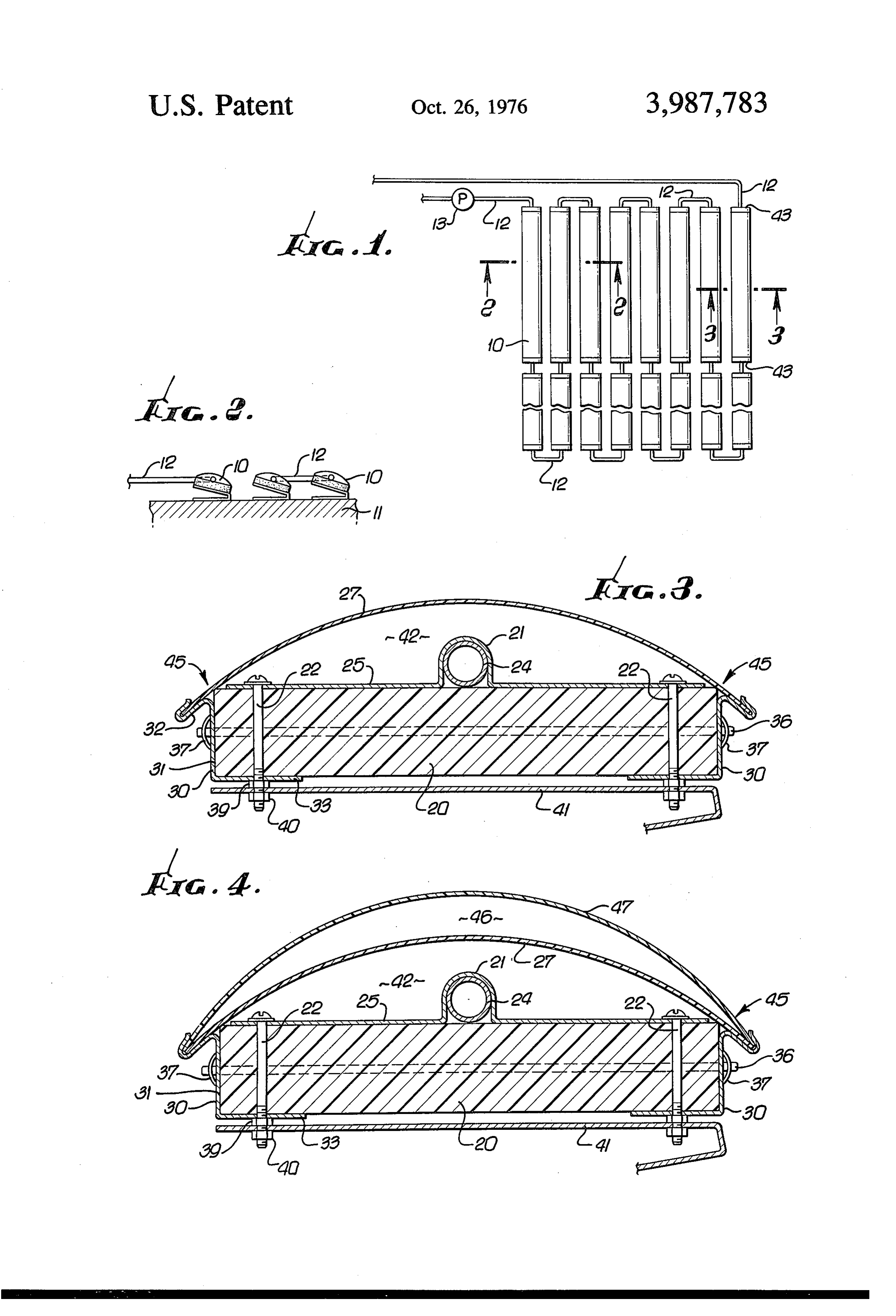
SOLAR HEATING PANEL. . with a heat collector 21 mounted on the top of the base as by bolts 22. Various forms of heat collectors may be
BACKGROUND OF THE INVENTION utilized and a preferred structure is shown in FIG. 3, This invention relates to solar heating and in particu consisting of a metal tube 24, with a metal plate 25 lar to a new and improved solar heating panel. Solar fitted tightly around the tube for good heat transfer energy is in-one sense free, but the equipment for col from the plate to the tube. The plate typically is of lecting and transporting the heat from the sun can be aluminum and preferably has an 'etched upper surface expensive, troublesome and unreliable. Accordingly it 10 with a black coating for maximum heat absorption. is an object of the present invention to provide a new A cover 27 is mounted on the base 20 and preferably and improved solar heating panel suitable for use with is a thin sheet of clear flexible plastic. a plurality of similar panels in an array, which panels Mounting clips 30 are provided at each edge of the are inexpensive and reliable, substantially trouble-free base 20 for receiving the cover 27. The clips preferably and durable, and easy to install and maintain. are bent from sheet aluminum and include a first por Heat collectors of various types have been used in the 15, tion 31 engaging the side of the base, a second portion past. One prior art heat collector consists of a metal 32 projecting outwardly and downwardly from the tube fitted with a metal sheet having an etched surface portion 31, and a third portion 33 at right angles to the with a special heat absorbing coating. The collector portion 31 projecting under the base 20. A channel is units are mounted on wooden blocks or on a roof or the provided in the clip portion 32 for receiving the cover like with the tubes interconnected for circulating wa 20 27.
ter, with the solar radiant energy being absorbed by the The clips 30 preferably extend the length of the panel metal sheets and transferred to the water for heating and are held in place by spaced rods 36 extending the water. A typical use for such an installation is heat through the base, and press-on clamps 37. ing a swimming pool. In the embodiment illustrated, the bolts 22 have a Some other solar heating devices are shown in U.S. 25 first nut 39 for holding the heat collector and clips to Pat. Nos. 260,657; 2,636,129; and 3,194,228. These the base, and a second nut 40 for holding a panel sup prior art devices incorporate various types of heat col port strip 41. The support strip 41 is not necessary but lectors and shields or covers which are complex and does provide for mounting the panels at an angle, as expensive and not readily suited for use as a cheap and 30 shown in FIG. 2.
simple swimming pool heater or the like. The cover is easily installed by sliding one edge into SUMMARY OF THE INVENTION one of the clips and then bending the cover to slide the opposite edge into the opposite clip. In the preferred
The solar heating panel of the present invention in embodiment cludes a heat collector mounted on an insulating base 35 there is a pressure illustrated, the clip is positioned so that with a cover carried on the base defining an air space the base at the corners engagement between the cover and between the cover and base. In the preferred configura cover and base along 45 the providing seals between the opposite edges of the air tion, the cover is a single sheet of flexible material space 42. The ends of the air space may be closed by carried in clips at opposite edges of the base with the caps 43 mounted at the ends of the base. cover in sealing engagement with the base at the top 40 Also, the clips 30 are preferably positioned so that surface and with the mounting clips below the top sur face. Suitable caps are provided at each end for closing the entire clip is below the top surface of the base. This the air space over the heat collector. In an alternative configuration the air space.
serves to prevent moisture from entering
The cover serves to protect the heat configuration, two spaced covers are utilized. collector from the elements so that the heat absorbing BRIEF DESCRIPTION OF THE DRAWING 45 surface does not deteriorate. The cover also serves to FIG. 1 is a top view of an array of solar heating panels maintain an insulating barrier of air over the heat col incorporating the presently preferred embodiment of lector to reduce heat loss to the surrounding atmo the invention; sphere. The configuration of FIG. 3 provides a good FIG. 2 is a sectional view taken along the line 2-2 of compression seal at the corners 45 with the simple flat FIG. 1; 50 cover and clip.
FIG. 3 is an enlarged sectional view taken along the An alternative embodiment is shown in FIG. 4 where line 3-3 of FIG. 1 showing one of the heating panels; a second cover 47 is carried in the clips 30 spaced and above the cover 27. This construction provides a sec FIG. 4 is a view similar to that of FIG. 3 showing an ond air space 46 between the covers 27, 47 for addi alternative embodiment of the heating panel of the 55 tional insulation from the atmosphere. invention. I claim:
Description of the preferred
1. In a solar heating panel, the combination of:
Embodiments
an elongate insulating base having a top and opposite edges;
Referring to FIGS. 1 and 2, a plurality of solar heat 60 a cover;
ing panels 10 is mounted on a roof or other suitable means for mounting said cover on said base at said support 11 in an array, preferably oriented at an angle opposite edges with said cover in sealing engage as shown in FIG. 2 for optimum exposure to the sun. ment with said base defining an air space between The panels 10 are interconnected by tubing 12 and a said cover and base, pump 13 provides for circulating a fluid, typically wa 65 said cover mounting means including a clip at each ter, through the panels for heating the fluid. opposite edge of said base, each of said clips having A typical panel is in the order of 6 inches wide and a first portion engaging said base and a second twelve feet long. The panel includes a base 20 of a portion projecting outwardly and downwardly from 4 said base with a channel for receiving the edge of ward below said top defining an air space between . . said cover; . . . .. . said cover and base;
a heat collector mounted on said base; and said cover mounting means, including a clip at each means for closing the ends of said air space. opposite edge of said base, each of said clips having 2. A solar heating panel as defined in claim 1 wherein. 5 a first portion engaging said base and a second each of said clips has a third portion at right-angles to portion projecting outwardly and downwardly from said first portion and projecting under said base, and said base with a channel for receiving the edge of including means for joining said heat collector, base. said cover;
and clip third portion to a support strip.
3. A solar heating panel as defined in claim 1 wherein 10 means collector a heat for mounted on said base; and closing the ends of said air space.
said cover is flexible to, an arcuate position for sliding 5. A solar heating panel as defined in claim 4 wherein insertion into said channels of said clips. said cover is flexible to an arcuate position for sliding 4. In a solar heating panel, the eombination of an elongate insulating base having a top and opposite 15 insertion into said channels of said clips. edges; 6. A solar heating panel as defined in claim 4 wherein a cover, , said heat collector comprises a tube with a metal heat means for mounting said cover on said base at said absorbing plate affixed thereto.
opposite edges with said cover projecting down
Provenance
- Collection
- Patents citing this work
- Pages
- 4
- Method
- pdftotext (the PDF's own text layer) + pdftoppm 300dpi page scans
- Patent office record
- patents.google.com →
- Source
- Google Patents citing-documents table
- Assignee
- Hayward Powell
- Published
- 1976-10-26
- Transcribed from
- patentimages.storage.googleapis.com →