

patent · US4392482A
Solar heating panel arrangement
12 July 1983
Text
Page 1bibliographic recordscan →
United States Patent (19)
(Chang
54). SOLAR HEATING PANEL ARRANGEMENT
76 Inventor: Moo K. Chang, 1 1979 Iowa St., Los
Angeles, Calif. 90025
Related U.S. Application Data 63 Continuation-in-part of Ser. No. 73,644, Sep. 10, 1979, abandoned.
Foreign Application Priority Data
int. Cl.................................................. F24J 3/02 52 U.S. Cl. .................................... 126/440; 126/438;
1,093,498 4/1914. Thring................................. 126/440 1,302,363 4/1919 Graham .............................. 126/440 3,145,707 4/1958 Thomason ........................... 126/271 3,587,559 6/1971 Nonaka ............................... 126/271 3,866,285 2/1975 Clark ...... ... 29/157 R 3,929, 121 12/1975 Rogers ................................ 126/271 3,985,116 10/1976 Kapany ............................... 126/270 3,998,204 12/1976 Fuchs et al. ........................ 126/270 4,033,324 7/1977 Eckels ................................. 126/440
4,056,093 11/1977 Barger ................................. 26/440
4,111,186 9/1978 Ross et al............................ 126/271 4,137,899 2/1979 Weslow ............................... 126/440 4,151,829 5/1979 Wilson ........ ... 126/438 4,284,068 8/1981 Gunderson .......................... 126/438
FOREIGN PATENT DOCUMENTS
55-30994 10/1970 Japan ................................... 126/440 Primary Examiner-James C. Yeung
Attorney, Agent, or Firm-Nilsson, Robbins, Dalgarn, Berliner, Carson & Wurst
A solar heating panel arrangement and method wherein a plurality of spherical lenses transmit and focus solar radiation onto the upper surface of a fluid passage for various relative positions of the sun. The upper surface of the passage is in heat transfer proximity to the fluid therein, causing solar radiation focused thereon to be transferred to the fluid in the form of heat. Solar radia tion not directly incident on the lenses may be reflected onto them to increase the amount of solar energy avail able for transfer to the fluid. A supplementary insulating flow of fluid may also be provided above the passage to absorb heat passing upwardly therefrom and retain the heat within the system.
24 Claims, 10 Drawing Figures
Drawings
Page 2drawing sheetscan →
Page 3drawing sheetscan →
Page 4drawing sheetscan →
Page 5drawing sheetscan →
Page 6drawing sheetscan →
Page 7drawing sheetscan →
Page 8scan →
any cover of the type disclosed would permit substan
SOLAR HEATING PANEL ARRANGEMENT tial amounts of heat to be lost. In addition, each lens of the Thring and Barger pa
This is a continuation-in-part of application Ser. No. tents is able to produce only a single heated area on the 73,644, filed Sept. 10, 1979, new abandoned. 5 corresponding hemispherical surface, that area repre BACKGROUND OF THE INVENTION senting the solar radiation which is directly incident on the lens. The amount of heat transferred to the fluid is
This invention relates generally to the solar heating thus severely limited by the size of the lenses used. art and more particularly to a novel solar heating panel Therefore, it is desirable to provide a solar heating arrangement and method wherein solar radiation is O panel able to more efficiently convert incident solar focused by a plurality of spherical lenses for transfer to radiation to usable thermal energy stored in a fluid. a fluid in the form of heat. SUMMARY OF THE INVENTION There have heretofore been proposed several types of solar heating panels for absorbing energy from the sun Briefly, the present invention comprises a solar heat and transferring it to a fluid passed through the panels. 15 ing panel arrangement having a plurality of spherical The heated fluid may generally be either a fluid such as lenses for transmitting and focusing solar radiation and water for consumption in a heated state or a recirculat a fluid passage structure having upper and lower spaced ing fluid fo transfer of thermal energy from the solar apart boundary portions defining a series of relatively panel to another device. In cases where consumable thin hemispherical fluid passages, the upper boundary fluid is heated, the fully heated fluid may be passed to an 20 portion or portions being in heat transfer proximity to insulated reservoir for storage until needed. fluid within the passage and having upper surfaces Prior solar heating panels often incorporate a plural which include the focal points of the spherical lenses for ity of fluid-carrying pipes or other conduits directly solar radiation of various directions. Solar radiation exposed to the sun's radiation. A portion of the incident incident on the lenses is thus focused on the upper sur radiation is thus absorbed by the pipes in the form of 25 face portions to heat those portions and be transferred heat, and a portion of that heat is transferred to the to the fluid within the passage in the form of heat. fluid. While panels of this type cause the temperature of The spaces between the lenses and the respective the fluid to increase, the efficiency of such panels suffers upper surfaces are preferably closed and may be cov substantially from limitations on heat transfer between ered by a substantially flat transparent heat insulating the pipes and the fluid passing therethrough. Since the 30 member engaging the lenses along meridians thereof. amount of heat transferred from one element to another Structures are preferably provided to reflect addi is directly related to the temperature gradient between tional solar radiation onto the lenses, producing addi the two elements, heat transfer from pipes uniformly tional points of focused radiation to heat the fluid. heated by the sun is limited by the relatively low uni These structures may be multifacetive reflective ele form pipe temperatures obtainable through solar irradi 35 ments positioned adjacent and partially about the re ation. Solar panels of this type may also be limited in spective lenses.
efficiency by an inherent dependence of their operating A passage may also be provided for directing a ther characteristics on the relative position of the sun. As the mally insulating flow of fluid past the hemispherical sun moves across the sky through the course of a day, passages, this insulating flow passage being upstream of the amount of solar radiation reaching the pipes or the hemispherical passages to cause heat escaping from other conduits may fall far below the desired level. the hemispherical passages to be absorbed by the insu Tracking mechanisms have been proposed for chang lating flow and maintained within the system. The insu ing the orientation of solar panels during the day to lating flow passage may include a series of substantially follow the sun as it crosses the sky, however, such flat annular fluid conduits positioned horizontally over mechanisms are themselves wasteful of energy and 45 the hemispherical passages at locations essentially about considerably complicate solar heating systems. the lenses. A layer of heat insulating material may also U.S. Pat. No. 1,093,498 issued to Thring discloses a be provided above the insulating flow passage to inhibit solar heating panel having an array of spherical lenses heat transfer between that conduit and the ambient air, projecting into hemispherical recesses formed in the the layer intersecting the lenses adjacent meridians upper surface of a water tank and separated from the 50 thereof. The insulating flow passage and the hemispher surfaces of the recesses by a relatively small distance. ical passages may be constructed and arranged to main Solar radiation incident on the spherical lenses is di tain the fluid in a pressurized state to prevent vaporiza rected onto the surfaces of the hemispherical recesses tion thereof, or may be constructed in a terraced fashion for the various positions of the sun. However, the vol to permit a gravity induced flow of fluid downwardly ume of water in the tank is substantial and the flow path 55 through the insulating flow passage. In the latter case, near the top of the tank is relatively obstructed, causing the gravity induced flow also forces the fluid upwardly the fluid flow rate past many points in the tank to be through the hemispherical passages. very slow. At those points, heated fluid would tend to The method of the present invention involves gener remain near the location at which it picked up its heat, ally the method practiced by the above-described appa reducing the temperature differential between the re ratus. Additional solar radiation may be reflected onto cesses and the fluid. The rate of heat transfer would thus the spherical lenses as they are irradiated by the sun, be reduced, as well. causing more heat to be concentrated on the heat ab U.S. Pat. No. 4,056,093 issued to Barger discloses a sorbing surfaces than is the case with direct irradiation solar heater having a single spherical lens positioned alone.
over a thin hemispherical flow passage for heating a 65 The method of the present invention may also include fluid therein. The lens is positioned under a transparent the initial step of passing the fluid supplied to the system hemispherical cover which insulates the lens assembly above the heat absorbing upper surfaces in a supplemen against heat dissipation to the atmosphere. However, tary insulating flow, for absorption of heat escaping 9 upwardly from the heated portions of the panel. The The reflection of additional solar radiation onto the supply fluid is then passed through the hemispherical lenses significantly increases the amount of solar energy passages for further heating, carrying with it an amount entering the system and thus permits much higher fluid of heat which would otherwise be lost from the system. temperatures to be obtained. Sunlight directly incident It is an object of the present invention to provide a on each lens is focused at a predetermined single point solar heating panel and method to more efficiently cap-. on the corresponding upper surface portion. This focal ture the energy embodied in incident solar radiation and point of sunlight is unaffected by the reflection process transfer the enery to a fluid in the form of heat. and continues to make its thermal contribution. How It is another object of the present invention to pro ever, the light reflected onto the particular lens is also vide a simple and inexpensive solar heating panel and 10 focused on the upper surface portion, producing at least method for maximizing the amount of solar energy one additional focal point of sunlight to heat the fluid captured and utilized throughout the daylight hours, passing beneath. The thermal contribution of the addi irrespective of the position of the sun in the sky. tional focal points is quite substantial and represents It is yet another object of the present invention to energy which otherwise would not impinge upon the provide an inexpensive solar heating panel able to func 15 lens. The heating capacity of each hemispherical pas tion over a long period of time with virtually no mainte sage is thus greatly increased, enabling fewer such pas nance or attention. sages to be used and substantially higher fluid tempera The solar heating panel of the present invention effi tures to be obtained.
ciently converts incident solar radiation to thermal en Optimal performance is achieved when a three ergy in a passing fluid by convergence of the incident 20 faceted reflective structure is disposed vertically behind radiation onto one or more upper boundary portions of each lens on the upper surface of the panel, producing a fluid passage. Because the upper surfaces of the upper as many as three additional focal points of sunlight on boundary portions include the focal points of a plurality the particular boundary portion. The exact number of of exposed spherical lenses for solar radiation of various additional focal points per lens can vary during the day, directions, incident solar radiation is converged on the 25 but should never be less than one. upper boundary portions throughout the day. The The insulating flow of supply fluid over the heated points of convergence are heated to a temperature of portions of the panel minimizes the amount of energy between 300 and 500 Celsius, producing a tremen dissipated upwardly therefrom. Energy that would dously high temperature differential between the upper boundary portions and the fluid flowing thereunder. 30 otherwise previously be lost from the system is absorbed by the unheated supply fluid and carried therewith
Heat transfer between the upper boundary portions and into the hemispherical the fluid adjacent the points of convergence is thus heat insulating materialfluid is passages. When a layer of placed above the insulating much more efficient than in prior devices.
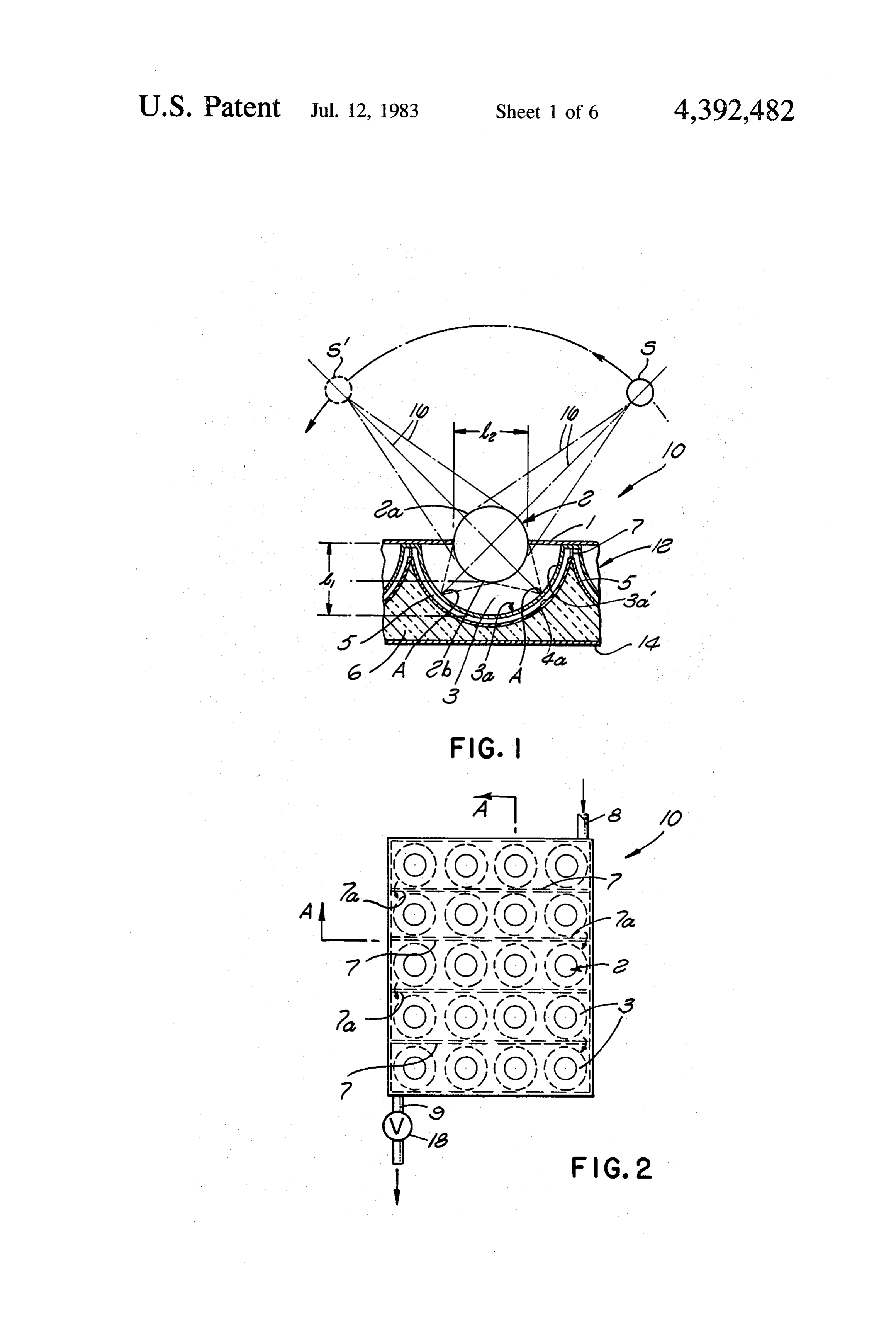
Formation of the upper and lower boundary portions flow, heat loss from the system is virtually eliminated. With the aforementioned apparatus and method, as interfitting hemispherical elements concentric with 35 water can be heated to temperatures as high as 100 the respective spherical lenses also maximizes fluid tur Celsius at substantially atmospheric pressure. Water bulence within the passage means, further increasing passing through the system receives heat from at least the efficiency of heat transfer from the upper boundary two points in each hemispherical passage, and is con portions to the passing fluid. Closure of the air spaces between the lenses and the upper boundary portions by stantly mixed by the turbulent flow therein to maximize an insulative glass plate engaging the lenses at meridians the temperature differential between the passage and thereof reduces heat loss to the atmosphere and forms a the fluid at those points. Furthermore, temperatures "hot box' of retained thermal energy in intimate approaching 150 Celsius are obtainable by pressurizing contact with each upper boundary portion of the fluid the water in the system to prevent vaporization. passage. The air within the hot boxes is maintained at a 45 BRIEF DESCRIPTION OF THE DRAWINGS temperature of between 100' and 200 Celsius when the The above and other objects of the present invention panel is exposed to the sun's rays, resulting in further may substantial heat transfer to the passing fluid along the tailedbedescription more fully understood from the following de taken together with the accompany upper surface portions. ing drawings, wherein similar reference characters refer When the panel of the present invention is provided 50 similar elements throughout, and in which: with upper and lower boundary portions each having a to FIG. 1 is a fragmentary vertical sectional view illus plurality of hemispherical elements and defining a single fluid passage coextensive with the boundary portions, trating a single heating cell of a first embodiment of the water in the passage can typically be heated to overall present invention, wherein the path of the sun across the temperatures up to 90° Celsius. The heating panels of 55 sky is indicated somewhat diagramatically; the present invention involve no moving parts and are FIG. 2 is a top plan view of the embodiment of the constructed in a simple manner to yield a product able present invention which incorporates the cell structure to provide efficient service over an extended period of of FIG. 1;
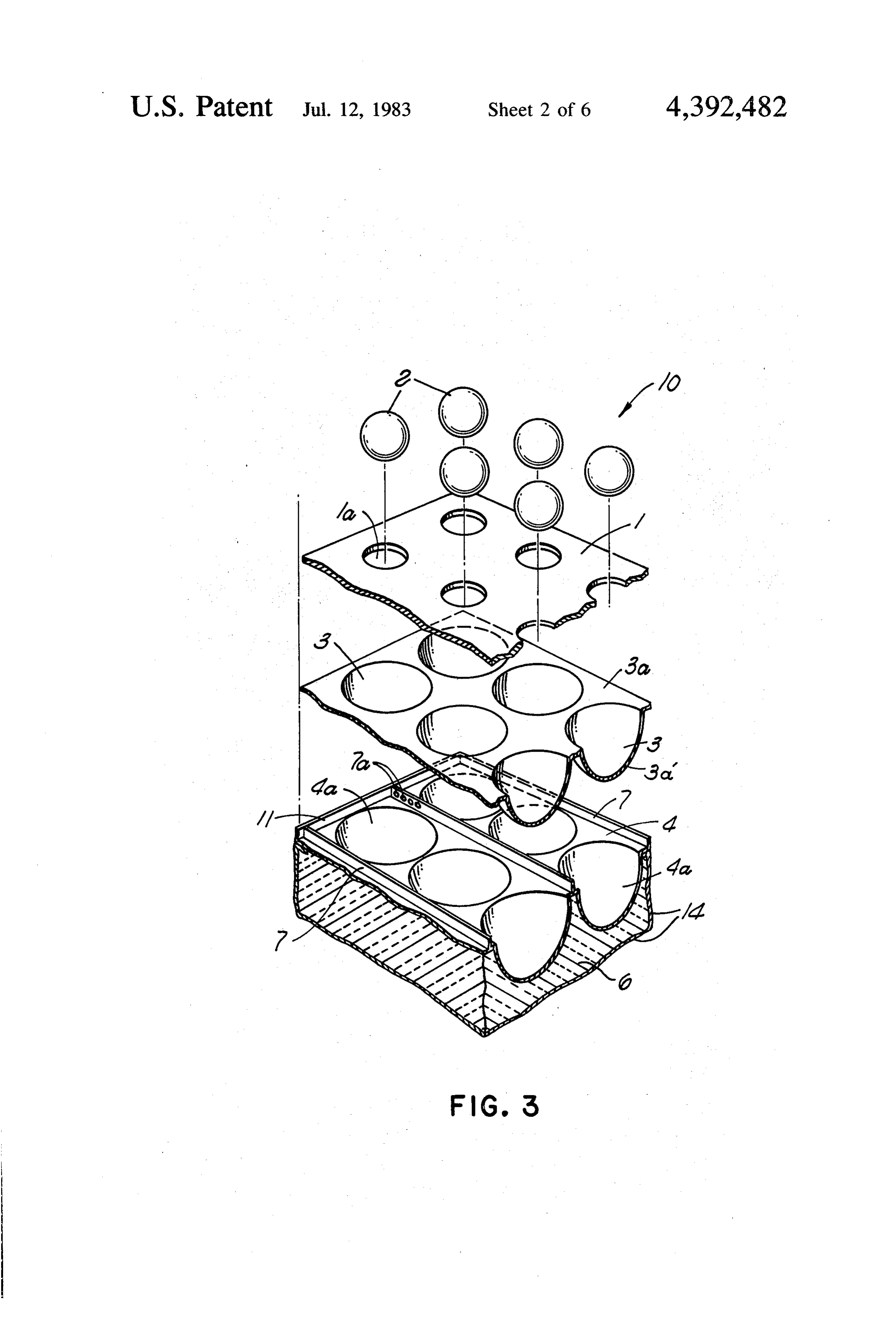
time. FIG. 3 is an exploded perspective view of the em The performance characteristics of the panel dis 60 bodiment illustrated in FIG. 2, fragmented along the closed herein are further enhanced by reflecting addi lineFIG. AA;
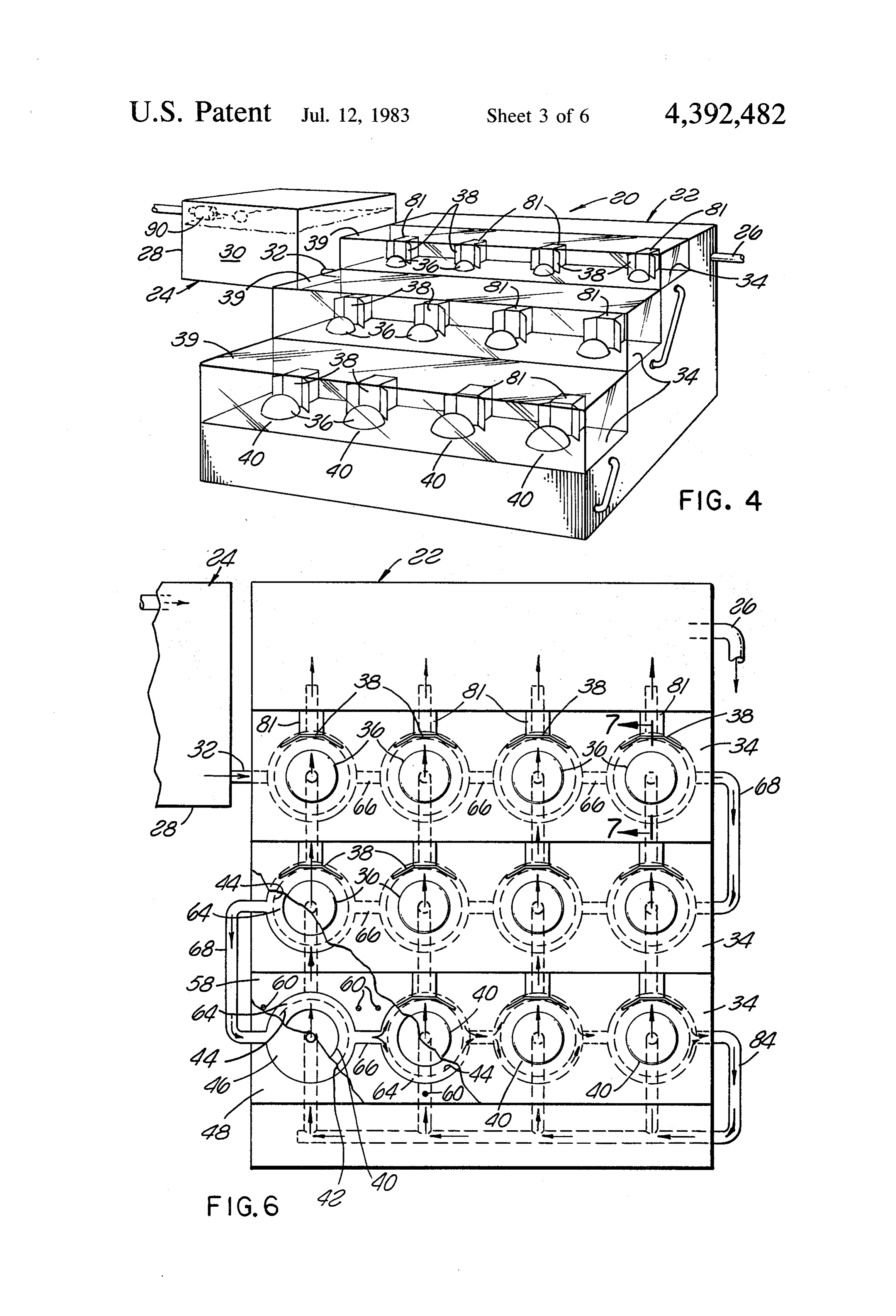
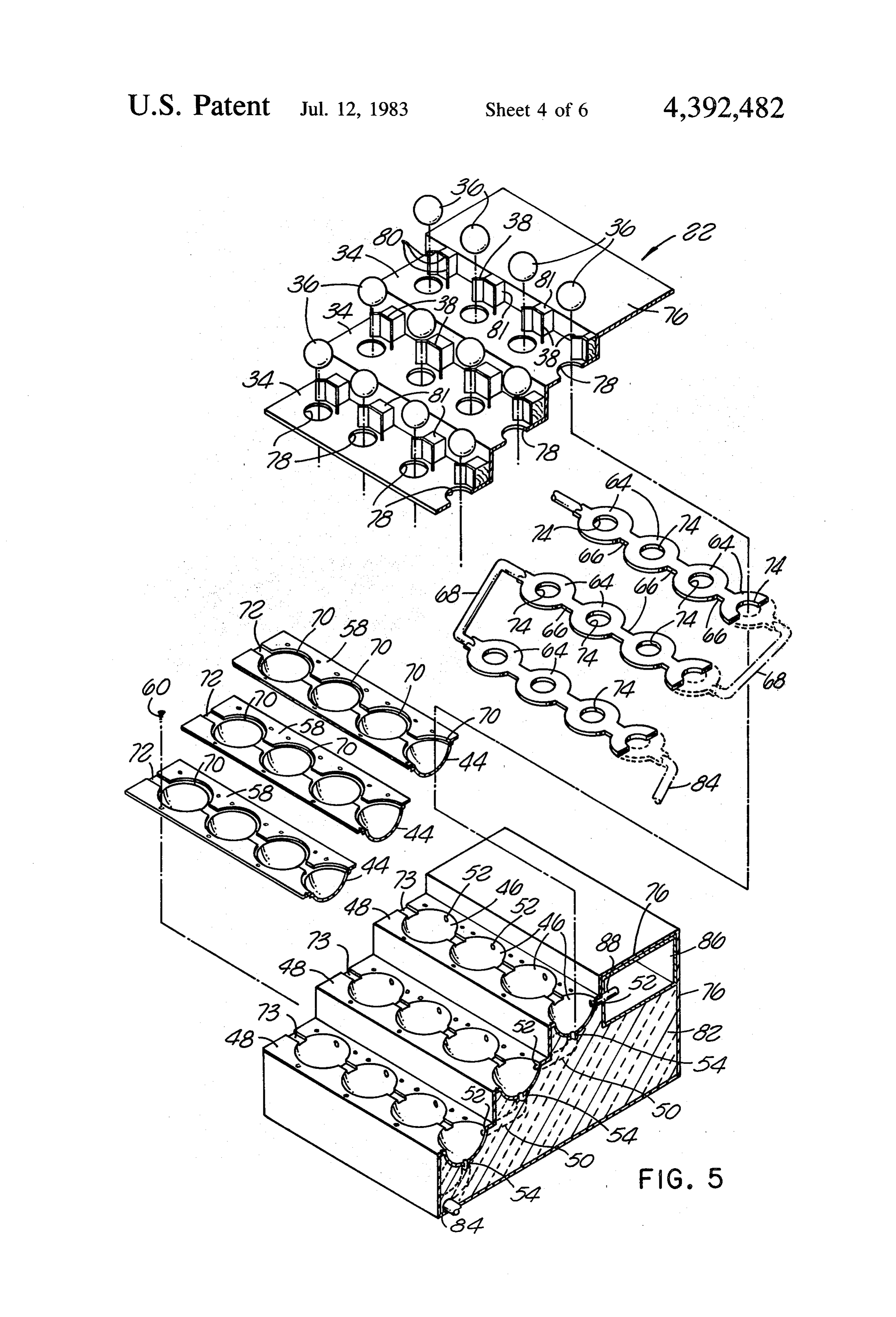
4 is a perspective view illustrating a second tional solar radiation on the lenses and establishing a supplementary insulating flow of supply fluid above the embodiment of the present invention; heated portions of the panel. For these purposes, the FIG. 5 is an exploded perspective view of a panel boundary portions can be formed as separate hemi 65 arrangement illustrated in FIG. 4, with the protective spherical elements joined in pairs to define discrete fluid . glass covers, removed therefrom; passages which are connected to form a parallel/series . FIG. 6 is a top plan view of the embodiment of FIG. flow network of the type disclosed. . . . .. . . . . ." 4, partially broken away;
Page 10scan →
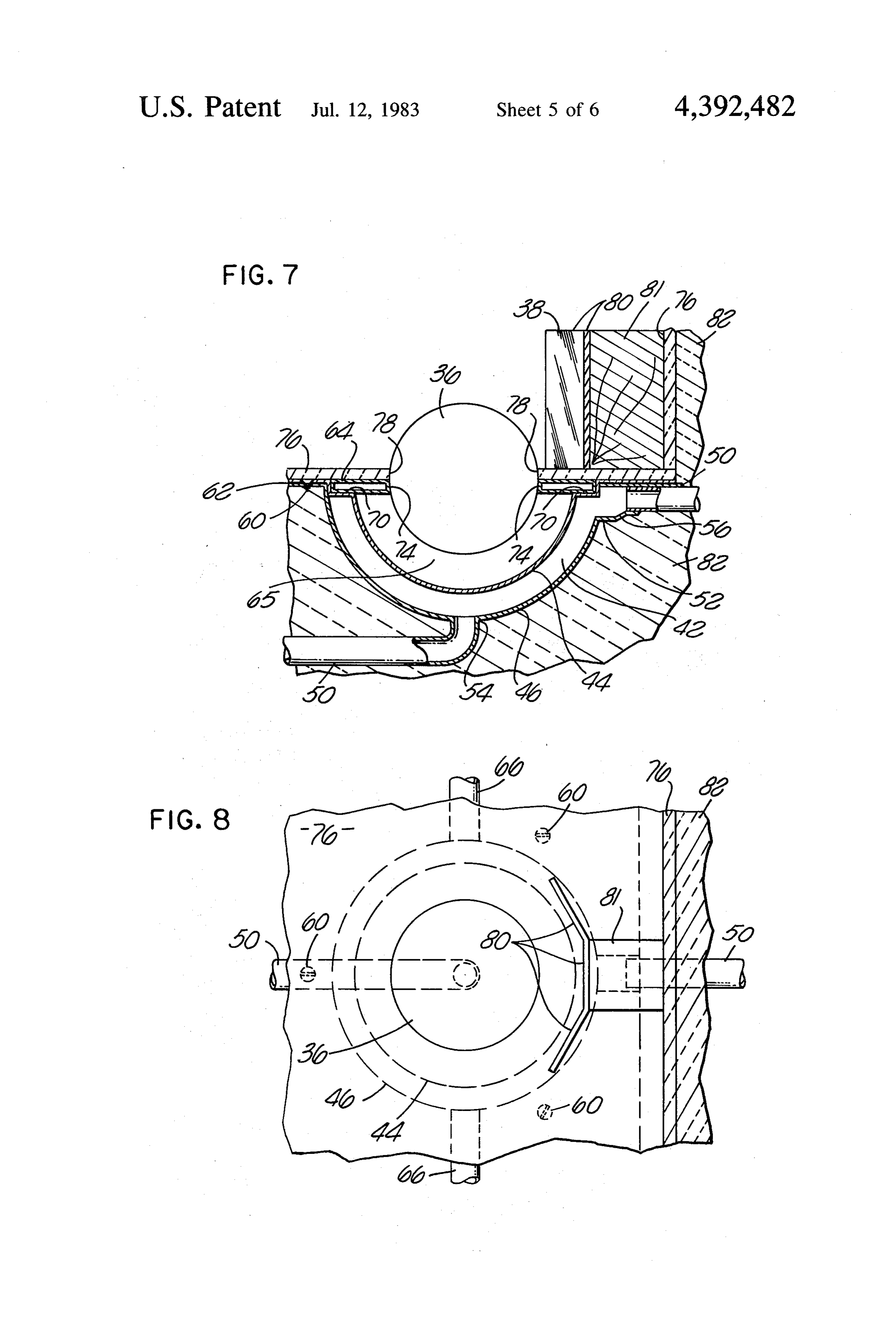
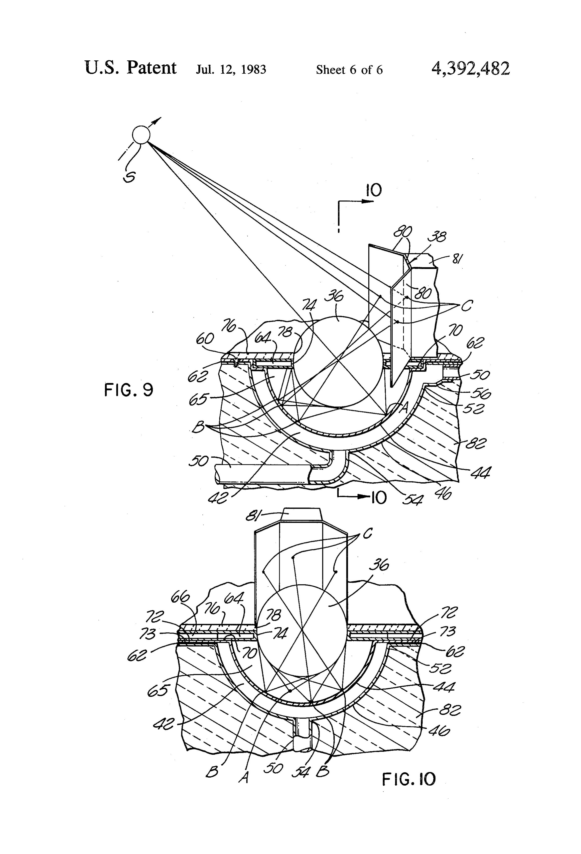
FIG. 7 is a fragmentary vertical sectional view of a In the preferred embodiment of the present invention, single heating cell of the second embodiment of the the radius L1 of the hemispherical closed air spaces 3 present invention, taken along the line 7-7 of FIG. 6; may be equal to the focal distance from the centers of FIG. 8 is a fragmentary top plan view of the single the respective spherical lenses 2. This distance will heating cell of FIG. 7; and - generally be somewhat less than the diameter L2 of the FIG. 9 is a vertical sectional view corresponding to spherical lenses. The focal points of the solar radiation FIG. 7, taken in perspective to more clearly show the incident on the spherical lenses 2 for the various relative optical paths of solar radiation transmitted by the corre positions of the sun are thus located on the upper sur sponding spherical lens. faces of the hemispherical recess portions 3a'. FIG. 10 is a vertical sectional view taken along the 10 The various components of the embodiment 10 may line 10-10 of FIG. 9, also in perspective. be constructed of any suitable materials possessing the properties described above and able to withstand ex
DESCRIPTION OF THE PREFERRED treme temperatures, sustained contact with the fluid EMBODIMENT used, and prolonged ultraviolet irradiation from the sun. Referring now to the drawings, there is illustrated, in 15 The made spherical lenses 2 and the upper plate may be of glass or heat resistive synthetic resin, however,
FIGS. 1, 2 and 3 thereof, a first embodiment of the present invention, generally designated 10. The embodi the plate 1 is preferably made of a heat blocking mate ment 10 generally comprises a plurality of spherical rial such as heat insulative glass. Heat insulative glass has a large number of closed air cavitites therein for lenses 2 held in position relative to a fluid passage appa 20 blocking ratus 12 by a transparent upper plate 1. the conduction of heat across the glass without interferring
The fluid passage apparatus 12 includes upper and upper boundary with the passage of light therethrough. The lower boundary portions 3a and 4, respectively, interfit metal or any other portion 3a may be formed of plastic, ting with each other to form a relatively thin passage 5 temperatures in the suitablerange of material able to withstand 300 to 500 Celsius. The therebetween. The boundary portions 3a and 4 are pro 25 upper surface of the hemispherical recess portions 3a' of vided with similar arrays of hemispherical recess por the upper boundary portion 3a may be coated with a tions 3a' and 4a, respectively, concentric with the heat absorptive material such as a special paint or metal spherical lenses 2. The passage 5 is thus formed of a lic plate designed to absorb rather than reflect the ma series of interconnected relatively thin hemispherical jority of the infrared radiation incident thereon. The spaces. As shown most clearly in FIGS. 2 and 3, the 30 lower boundary portion 4 may also be made of any passage 5 is divided into rows of the recess portions 3a' suitable material, but it need not have as high a resis and 4a by parallel partitions 7 having openings 7a at tance to deterioration from high temperatures since it is alternating ends thereof. A single continuous fluid pas not exposed to the focused rays of the sun. As discussed sage is thus formed within the embodiment 10. Fluid above, the lower boundary portion 4 may simply com enters the passage 5 through the inlet 8 and travels a 35 prise the upper surface of the body of heat insulating tortuous alternating path, as indicated in FIG. 2, material 6 forming the base of the embodiment 10. The through the various rows of hemispherical spaces form parallel partitions 7 may likewise be made of any suit ing the passage 5. Fluid reaching the end of the passage able material which will not deteriorate from contact 5 is directed into an outlet 9 controlled by a valve 18. with the fluid or from exposure for prolonged periods The thin tortuous path through the passage 5 creates 40 of time to the temperature of the fluid. substantial turbulence in the passing fluid, greatly en The lenses 2 may be secured within the openings 1a hancing mixture of the fluid. of the upper plate 1 by any conventional means, such as The lower boundary portion 4 of the fluid passage a heat resistive cement compound. Likewise, the air apparatus 12 may be backed with a heat insulating mate tight seals between the upper plate 1 and the upper rial 6 to minimize the downward escape of heat from 45 boundary portion 3a may be formed with cement or any the fluid. Alternatively, the lower boundary portion 4 other binding agent, as may the points of connection can be formed integrally with the heat insulating mate between the parallel partitions 7 and the two boundary rial 6 such that the upper surface of the lower boundary portions 3a and 4.
portion 4 is actually the surface of the insulating mate In operation, the embodiment 10 is oriented in a man rial. A skin 14 at the bottom and sides of the fluid pas 50 ner causing the lenses 2 to receive light from the sun sage apparatus 12 may be provided to act as a contain during the majority of the daylight hours. The sun is ment medium for the insulating material 6. designated in FIG. 1 by the letter S and is shown dia The transparent upper plate 1 extends across the top grammatically tracing an arc in the indicated direction of the fluid passage apparatus 12 and is attached to the from the full line position S to the broken line position upper boundary portion 3a in a sealing relationship 55 S', during which time it emits radiation designated 16. A around each of the hemispherical recess portions 3a'. portion of the radiation 16 is incident on each of the The upper plate 1 is provided with an array of circular lenses 2 and is focused thereby at a point designated openings 1a centered over the hemispherical recess “A” on the light absorptive upper surface of the corre portions 3a' for reception of the spherical lenses 2. The sponding upper boundary portion 3a. The focused rays spherical lenses 2 are positioned within the openings a 60 of the sun at the point A causes the upper boundary such that the upper plate 1 closely engages the lenses 2 portion 3a to be heated at that point to a constant tem along meridians of the lenses and is bonded thereto in perature of between 300 and 500 Celsius. The temper air tight sealing relationship. The lenses 2 are thus con ature differential is thus very high between the portion centric with the hemispherical recess portions 3a' with 3a at the point A and the water or other fluid within the the upper halves 2a projecting above the upper plate 1 65 passage 5 adjacent thereto, yielding a high rate of heat and the lower halves 2b extending downwardly there transfer between those elements. The fluid also travels from to form hemispherical closed air spaces 3 between through the passage 5 with substantial turbulence, effec the lenses 2 and the upper boundary portion 3a. tively mixing the water to maintain the highest possible 11 temperature differential and thus the highest possible passages 42. The flat portions of the upper and lower rate of heat transfer at the point A. At the same time, the plates 58 and 48 are held together in sealing relationship air confined within the hemispherical closed air space 3 by a plurality of screws or other fasteners 60. A yielding is heated both by direct solar irradiation and the high material 62 (FIG. 7) may be confined between the flat temperature of the boundary portion 3a at the point A, surfaces of the upper and lower plates to aid in forming causing the air to reach a temperature between 100 and a seal.
200 Celsius. The closed air space 3 thus acts as a "heat A series of thin annular conduits 64 are positioned box' or a heat receiving compartment from which heat horizontally above the hemispherical passages 42 and cannot easily escape upwardly through the glass plate 1 about the respective spherical lenses 36 for conduction and can only pass through the boundary portion 3a to 10 of an insulating flow of supply fluid over the hemispher the fluid within the passage 5. Since the maximum tem ical passages and the air spaces 65 between the lenses perature of the fluid is generally between 80 and 90' and the other boundary portions 44. The annular con Celsius, a substantial temperature differential exists at duits 64 are connected in series by short conduit sec all times between the air in the space 3 and the fluid. tions 66 between annular passages on the same step of This temperature differential causes heat transfer 15 the panel arrangement and longer conduit sections 68 through the entire hemispherical recess portion 3a' and running from one step to the next. The first conduit 64 produces a significant additional heating effect in the in the series is connected to the supply tank 28 through embodiment 0. the connecting conduit 32 described above. The outer The embodiment 10 is thus extremely efficient and is edge of each annular conduit 64 may be received within able to heat water to temperatures up to 90° Celsius, 20 an annular groove 70 provided about the corresponding whereas most conventional heating panels are unable to upper boundary portion 44 in one of the upper plates 58. heat water above 70' C. Similarly, the short sections 66 between the annular FIGS. 4 through 10 illustrate a second embodiment conduits may be received within grooves 72 and 73 of of the present invention, generally designated 20. The the upper and lower plates 58 and 46, respectively. The embodiment 20 generally comprises a panel arrange 25 annular conduits 64 and sections 66 are thus recessed ment 22 connected to a fluid supply 24 and having an into upper plates 58 to provide a substantially uniform outlet 26 for heated fluid. surface, with the inner edges 74 of the conduits 64 gen The fluid supply 24 may include a tank 28 in which erally abutting the spherical lenses 36. supply fluid 30 is maintained at a predetermined level. As shown in FIG. 5, the entire panel arrangement 22, The tank 28 is connected to a fluid inlet of the panel 30 except for the spherical lenses 36 and the reflective arrangement 22 by a conduit 32 located below the level structures 38, is clad in a layer 76 of asbestos board or of fluid in the tank. Thus, the fluid 30 is supplied to the other suitable material. The layer 76 extends over the panel arrangement 22 at a constant pressure. stepped portion of the panel arrangement 22, as well as The panel arrangement 22 is provided with a plural the sides and bottom thereof. On the steps 34, the layer ity of horizontal steps or terraces 34 carrying a number 35 76 extends to the lenses 36 and is bonded thereto along of spherical lenses 36 and corresponding reflective meridians of the lenses. Thus, the lenses 36 are sup structures or mirrors 38. Each of the steps also includes ported within openings 78 of the layer 76 with the upper a transparent cover 39 to protect the lenses and mirrors halves of the lenses exposed to sunlight. and prevent dirt from accumulating thereon. In the The reflective structures 38 are multifaceted and configuration shown, each of the three steps 34 is pro extend partially about the respective lenses 36 along the vided with four spherical lenses 36, the lenses being rear thereof. As illustrated, each of the reflective struc arranged in four side by side rows 40 running from one tures has three facets formed by separate mirror sec step to the next. It will, of course, be understood that tions 80 arranged vertically and contiguously about the the numbers of steps and rows in the figures have been rear edge of the corresponding lens, the central sections chosen solely for illustrative purposes. The exact num 45 being anchored to the asbestos layer 76 through spacer ber of these elements in a device of the type disclosed blocks 81 which are preferably made of wood and are herein will depend upon a number of factors, including fixed to the asbestos layer 76. This configuration has the amount of heated water required and the tempera been found to reflect the maximum amount of additional ture to which the water is to be heated. solar radiation onto each lens without obstructing the Referring now primarily to FIGS. 5 through 8, a thin 50 paths of radiation directly incident on the various hemispherical fluid passage 42 is formed directly be lenses.
neath and concentrically with each of the lenses 36 by The base or core of the panel arrangement 22 is pref. upper and lower boundary portions 44 and 46, respec erably a solid mass 82 of insulating material. The mass tively. The lower boundary portions 46 are formed as 82 can be a cellular material which has both substantial aligned hemispherical depressions in a series of lower 55 structural strength and good heat insulating properties. plates 48 extending essentially along the steps 34 of the The mass 82 thus provides an insulating backing for the panel arrangement. The lower boundary portions 46 are lower plates 48 and the lower hemispherical portions 46 thus arranged in rows corresponding to the rows 40 thereof, as well as the conduits 50 and the other ele described above. The boundary portions in each such ments of the panel arrangement 22.
row are connected in series by conduits 50 joining the 60 The fluid conductive path within the panel arrange upper rim 52 of each boundary portion 46 with the ment 22 is completed by a manifold 84 connecting the lower end 54 of the next higher boundary portion. As last annular conduit 64 in series with the hemispherical seen most clearly in FIG. 7, the conduits 50 are prefera portions 46 at the lowest of the steps 34. The manifold bly connected to the upper rims 52 of the lower bound 84 communicates with the lower ends 54 of the lower ary portions through enlarged transition sections 56. 65 boundary portions 46. A tank 86 is provided adjacent The upper boundary portions 44 are similarly formed the upper step 34 to receive fully heated fluid. The as hemispherical depressions in upper plates 58 which hemispherical passages 42 at the upper step are con overlie the lower plates 48 to form the hemispherical nected to the tank 86 by a plurality of conduits 88 ex 12 tending outwardly from the upper rims thereof. Fully hemispherical fluid passages will be made of copper heated fluid from the hemispherical passages is thus sheet, while the lower boundary portions 46 and the permitted to flow through the conduits 88 to the tank 86 conduits 50 will be made of either copper or a ferrous for eventual withdrawal through the outlet 26 described metal. The upper surfaces of the boundary portions 44 above. may be coated with a heat absorptive material similar to The path of fluid through the system as a whole can the coating described above in relation to the recess be seen most clearly in conjunction with FIG. 6. Supply portions 3a' of the embodiment 10. The yielding mate fluid 30 enters the tank 24 and is maintained at a prede rial 62 may be a thin coating or gasket of rubber, neo termined level by an automatic valve mechanism 90 prene or other suitable material between each pair of shown schematically in FIG. 4. The fluid within the 10 upper plates 58 and lower plates 48. The thin annular tank 24 is thus passed at constant fluid pressure through conduits 64 and the associated conduit sections 66 and the series of thin annular conduits 64 as an insulating 68 can likewise be made of either copper of a ferrous fluid flow 92. The insulating flow 92 proceeds in a zig metal. The spherical lenses 36 may be made of glass or Zag fashion down the steps of the panel arrangement 22 plastic, and may be held in place within the respective until it reaches the end of the bottom step. At this point, 15 openings 78 by a suitable cement or adhesive compound the fluid 30 of the insulating flow 92 is passed through (not shown). The solid mass 82 of insulating material the array of hemispherical passages 42 as a principal may comprise a suitable foam material formed about the heating flow 94. The principal flow 94 is a parallel flow undersides of the lower plates 48, the conduits 50 and directed upwardly along the various rows of hemi the manifold conduit 84. A number of commercially spherical passages corresponding to the rows 40 of 20 available plastic foam compositions can be foamed in spherical lenses. The insulating flow 92 is in series with placed about these elements to provide a barrier against the principal heating flow 94 and located upstream the downward loss of heat from the system and serve as thereof. Due to the configuration of the tank 24 and the a base for the panel arrangement 22. The basic stepped series of annular conduits 64, the insulating flow 92 is or terraced configuration of the panel arrangement 22 gravity induced and can be sufficient to produce the 25 can thus be simply and inexpensively provided by the principal flow 94 through the panel arrangement. This mass 82.
is true when the level 96 of supply fluid in the tank 24 is In operation, supply fluid from the tank 28 is passed at above the level of heated fluid within the tank 86. Static constant pressure through the panel arrangement 22, as pressure produced by the effects of gravity on the fluid controlled by a valve (not shown) in the outlet conduit 30 in the system, in combination with the natural ten 30 26. The fluid 30 is initially passed along the steps 34 in dency of heated fluids to rise, is then sufficient to induce the form of the insulating flow 92. During this time, the the flows 92 and 94 on a continuous basis. An outlet flow 92 acts as a barrier to heat transfer in an upward flow valve (not shown) may be placed in the outlet line direction from the hemispherical fluid passages 42 and 26 to regulate these flows. the air spaces 65. Heat which might otherwise be lost to As seen most clearly in FIGS. 9 and 10, radiation 35 the atmosphere is absorbed by the insulating flow 92 for from the sun "S" is focused at a plurality of points on reintroduction into the principal heated flow 94. The each of the upper boundary portions 44. The radiation insulating flow 92 is thus gradually preheated to a tem directly incident on a particular lens 36 is focused at a perature of between 30 and 40° Celsius as it progresses point designated "A" on the boundary portion 44. The downwardly along the panel arrangement 22. Heat loss point A is essentially in line with the incident radiation, from the insulating flow itself is minimized by the insu on the opposite side of the lens 39 from the sun. lating layer 76. The insulating flow 92, in combination During most of the day, additional solar radiation is with the insulating layer 76 and the insulating mass 82, reflected onto each lens 36 by one of the reflective virtually eliminates heat loss from the system. structures 38 and is focused by the lens at one or more Preheated fluid from the insulating flow 92 is con additional focal points "B" on the boundary portion 44. 45 ducted by the manifold 84 into the rows of hemispheri This additional radiation impinges upon one or more of cal passages 42. The flow 92 is thus transformed into the the mirror sections 80 at areas "C" thereon and repre principal flow 94 which is heated by the focal points A sents radiation which otherwise would not reach the and B of solar radiation on the upper boundary portions lens 36. The total number of focal points on the bound 44. As described above in relation to the embodiment ary portion 44 during the hours of usable sunlight will 50 10, the focal points are heated to temperatures between vary from a minimum of two to a maximum of four. One 300' and 500 Celsius and the temperature gradient of these points will be the point A of radiation directly from the focal points to the principal flow of fluid 94 is incident on the particular lens 36, and the remaining one maximized by the turbulence of the flow. However, in to three points will correspond to additional radiation this embodiment the focal points B are heated by addi focused onto the lens by the reflective structure 38. 55 tional focused radiation which impinges upon the lenses It has been found that the device of the embodiment 36 solely by virtue of the reflective structures 38. This 20 yields four focal points per lens for approximately 1: additional radiation represents a substantial increase in to 2 hours each day. Three focal points are then present the amount of solar energy entering the panel arrange for approximately 2 additional hours, and the number of ment 22, and all of the additional radiation is focused for points is reduced to two for the remaining 2 or more 60 efficient transfer to the fluid 30. Consequently, the fluid hours of usable sunlight. The location of the various 30 may be heated to a significantly higher temperature focal points A and B on the boundary portion 44 will, of using fewer stages or steps of hemispherical passages 42. course, also vary over time as the relative position of Although the panel arrangement shown in FIGS. 5 the sun varies. through 10 is provided with only three steps 34 of hemi The various components of the embodiment 20 may 65 spherical passages 42, it will be understood that the be constructed of any of the materials described above embodiment 20 may comprise any number of steps of for the corresponding components of the embodiment hemispherical passages depending upon the require 10. Preferably, the upper boundary portions 44 of the ments of a particular installation. The optimum number 13 of steps for most residential uses of the embodiment 20 through the passages and having upper surfaces is either four or five. It has been found that a heater of which include the focal points of the lenses for this type with four or five hemispherical passages in incident solar radiation of various directions; and each row is able to heat water to approximately 100', C. means for reflecting solar radiation onto the lenses for Temperatures of this magnitude enable the water or 5 transmission to the upper boundary portions, said other fluid heated by the embodiment 20 to power many reflecting means including a plurality of multifac conventional air conditioners, freezers and other cool eted reflective structures each comprising three ing devices. planar reflective portions arranged vertically about The number of rows 40 of spherical lenses and hemi a portion of one of the lenses; spherical passages will, of course, be determined by the 10 such that solar radiation is focused at a plurality of quantity of heated water desired. A device having a locations on each of said upper boundary portions greater number of rows 40 of hemispherical passages to heat said fluid, one of said locations representing will have the capacity to produce heated fluid at a pro radiation directly incident on the corresponding portionately higher rate. lens and the other location or locations represent The various fluid passages within the panel arrange 15 ing radiation reflected onto the lens by said reflect ment 22 can also be constructed to maintain the fluid 30 ing means.
in a pressurized state to prevent the fluid from vaporiz 2. The solar heating panel arrangement recited in ing when it is heated to a very high temperature. Thus, claim 1 wherein the three planar reflective portions are the fluid passages can be constructed to withstand ele substantially contiguous with one another. vated internal pressures and valves can be provided at 20 3. A solar heating panel arrangement comprising: the inlet conduit and the outlet 26 to hold the fluid a plurality of spherical lenses for transmitting and within the passages under pressure. This construction is focusing incident solar radiation; particularly useful when the fluid to be heated is water, fluid passage means having upper and lower bound since additional steps of hemispherical passages can ary portions defining a series of relatively thin then be provided for superheating the water. In this 25 hemispherical fluid passages concentric with said manner, fluid temperatures on the order of 150 Celsius lenses, respectively, and establishing an air space can be achieved. between each of the lenses and the respective As seen best in FIGS. 2 and 6, the embodiments 10 upper boundary portion, said upper boundary por and 20 are easily adaptable for use with any system tions being in heat transfer proximity to fluid flow requiring a heated fluid by simply connecting them into 30 ing through the passages and having upper surfaces the fluid circuit of the system through the inlets and which include the focal points of the lenses for outlet provided. The heated fluid may be used immedi incident solar radiation of various directions; ately or held for storage within an insulated vessel for means for reflecting solar radiation onto the lenses for use at a later time. In the case where the fluid to be transmission to the upper boundary portions; and heated is water in the plumbing system of a building, 35 means for producing a thermally insulating flow of heated water may be collected in an insulated reservoir said fluid past the passage means, the insulating and withdrawn as the need for hot water arises. flow means being upstream of the passage means It will be understood that, although the reflective and including a series of substantially planar annu structures 28 have been described only in relation to the lar fluid conduits positioned horizontally over the embodiment 20, the teachings herein relative to reflec passage means and the air spaces at locations sub tive structures and the method of using them are appli stantially about the lenses; cable to any solar heating panel having spherical lenses. such that solar radiation is focused at a plurality of Thus, reflective structures similar to the elements 38 locations on each of the upper boundary portions can be incorporated into the embodiment 10 with satis to heat the fluid, one of said locations representing factory results. Similarly, an insulating flow of supply 45 radiation directly incident on the corresponding fluid similar to the flow 92 described above can be set lens and the other location or locations represent up in the apparatus of the embodiment 10 to minimize ing radiation reflected onto the lens by the reflect heat loss upwardly therefrom. ing means, and heat escaping from the passage From the above, it can be seen that there has been means is absorbed by the fluid and carried thereby provided an improved solar heating panel able to effi 50 into the passage means.
ciently utilize incident solar radiation over the course of 4. The solar heating panel arrangement recited in a day to heat a fluid such as water to a high temperature, claim 3 which includes a layer of heat insulating mate without the need for moving the panel during the day to rial located above the series of substantially planar fluid keep it aligned with the sun's rays. The panel is also conduits to inhibit heat transfer between the conduits inexpensive to manufacture and is possessed of a long 55 and the ambient air, the layer of insulating material operation life. intersecting the lenses adjacent meridians thereof. The appended claims are intended to cover all varia claim 5. The solar heating panel arrangement recited in tions and adaptations falling within the true scope and 4 wherein the lenses are bonded to the layer of spirit of the present invention. insulating material.
I claim: 6. The solar heating panel arrangement recited in 1. A solar heating panel arrangement comprising: claim 5 wherein the layer of insulating material is asbes a plurality of spherical lenses for transmitting and tos board.
focusing incident solar radiation; 7. The solar heating panel arrangement recited in fluid passage means having upper and lower bound claim 3 wherein the conduits are connected in series ary portions defining a series of relatively thin 65 with each other and with the fluid passage means. hemispherical fluid passages concentric with said 8. The solar heating panel arrangement recited in lenses, respectively, said upper boundary portions claim 7 wherein said insulating flow means and said being in heat transfer proximity to fluid flowing fluid passage means are constructed and arranged to 14 maintain the fluid in a pressurized state to prevent va stantially about the lenses, to cause heat escaping porization of the fluid when high fluid temperatures are from the passage means to be absorbed by the fluid achieved. and carried thereby into the passage means. 9. The solar heating panel arrangement recited in 15. The solar heating panel arrangement recited in claim 7 wherein the hemispherical fluid passages are 5 claim 14 which includes a layer of heat insulating mate arranged in terraced fashion with a plurality of rows of rial located above the series of substantially planar fluid the passages running up the terraces. conduits to inhibit heat transfer between the conduits 10. The solar heating panel arrangement recited in and the ambient air, the layer of insulating material claim 9 wherein each of the rows comprises at least four intersecting the lenses adjacent meridians thereof. of the passages. 10 16. The solar heating panel arrangement recited in 11. The solar heating panel arrangement recited in claim 15 wherein the lenses are bonded to the layer of claim 9 wherein the passages within each of the rows insulating material.
are connected in series, and the rows are connected in 17. The solar heating panel arrangement recited in parallel with each other. claim 16 wherein the layer of insulating material is as 12. The solar heating panel arrangement recited in 15 bestos board.
claim 11 wherein the insulating flow means is con 18. The solar heating panel arrangement recited in structed and arranged to permit a gravity induced flow claim 14 wherein the annular fluid conduits are con of the fluid in a generally downward direction through nected in series with each other and with the fluid pas the series of conduits, said gravity induced flow forcing sage means.
the fluid upwardly through the rows of hemispherical 20 19. The solar heating panel arrangement recited in passages. claim 18 wherein the insulating flow means and the fluid 13. The solar heating panel arrangement recited in passage means are constructed and arranged to maintain claim 12 wherein each of the hemispherical fluid pas the fluid in a pressurized state to prevent vaporization sages has an upper rim and a lower end and is provided of the fluid when high fluid temperatures are achieved. with a fluid inlet and a fluid outlet for connecting the 25 20. The solar heating panel arrangement recited in passages in series, the fluid inlet extending upwardly claim 18 wherein the hemispherical fluid passages are into the lower end and the fluid outlet extending out arranged in terraced fashion with a plurality of rows of wardly from a point on the upper rim. the passages running up the terraces. 14. A solar heating panel arrangement comprising: 21. The solar heating panel arrangement recited in a plurality of spherical lenses for transmitting and 30 claim 20 wherein each of said rows comprises at least focusing solar radiation; four of the passages.
fluid passage means having a plurality of upper and 22. The solar heating panel arrangement recited in lower boundary portions defining a series of rela claim 20 wherein the passages within each of the rows tively thin hemispherical fluid passages concentric are connected in series, and the rows are connected in with said lenses, respectively, and establishing an 35 parallel with each other.
air space between each of the lenses and the respec 23. The solar heating panel arrangement recited in tive upper boundary portion, said upper boundary claim 22 wherein the insulating flow means is con portions being in heat transfer proximity to fluid structed and arranged to permit a gravity induced flow flowing through the passages and having upper of the fluid in a generally downward direction through surfaces which include the focal points of the lenses the series of conduits, said gravity induced flow forcing for incident solar radiation of various directions; the fluid upwardly through the rows of hemispherical such that solar radiation incident on the lenses is passages.
focused on the upper surfaces to heat the fluid 24. The solar heating panel arrangement recited in within the passage means; and claim 23 wherein each of the hemispherical fluid pas means for producing a thermally insulating flow of 45 sages has an upper rim and a lower end and is provided the fluid past the passage means, the insulating flow with a fluid inlet and a fluid outlet for connecting the means being upstream of the passage means and passages in series, the fluid inlet extending upwardly including a series of substantially planar annular into the lower end and the fluid outlet extending out fluid conduits positioned horizontally over the wardly from a point3konx the2k upper x xk rim.
passage means and the air spaces at locations sub 50
Page 15scan →
United states patent and trademark office
Certificate of correction
INVENTOR(S) : Moo K. Chang
It is certified that error appears in the above-identified patent and that said Letters Patent are hereby corrected as shown below:
Column l, line ).3 "fo" should be --for--. Column 3 line 8 "enery" should be --energy--. Column 9, line 4l "39" should be - -36--.
Column ill, line 2l "conduit and " should be -- conduit 32 eigned and Sealed this
Thirteenth O 2 y O f December 1983
Seal
Attest
Gerald j mossinghoff
Attesting Officer Commissioner of Patents and Trademarks
Provenance
- Collection
- Patents citing this work
- Pages
- 15
- Method
- pdftotext (the PDF's own text layer) + pdftoppm 300dpi page scans
- Patent office record
- patents.google.com →
- Source
- Google Patents citing-documents table
- Assignee
- Chang Moo K
- Published
- 1983-07-12
- Transcribed from
- patentimages.storage.googleapis.com →