

patent · US4175541A
Solar heating system
27 November 1979
Text
Page 1bibliographic recordscan →
Midgley
54 SOLAR HEATING SYSTEM
76 Inventor: Calvert H. Midgley, 2200
Gravenstein Hwy, Sebastapol, Calif.
(51) Int. Cl’................................................. F24J 3/02 (52) U.S. Cl. .................................... 126/429; 126/442;
58 Field of Search ....................... 126/270, 271, 400;
2,294,137 8/1942 Spofford .......................... 165/i79 X
3,875,925 4/1975 Johnston .............................. 126/270 3,894,685 7/1975 Keyes et al. ......................... 237/1 A 4,059,226 11/1977 Atkinson .............................. 126/400
all Ael
4,088,115 5/1978 Powell ................................. 237/1 A 4,088,266 5/1978 Keyes.................................. 237/1 A 4,094,300 6/1978 Young .................................. 126/271 Primary Examiner-Samuel Scott
Assistant Examiner-Larry Jones
A solar heating system comprising a collector panel with a plurality of beverage cans or the like received in holes drilled therethrough. The surfaces of the panel and the cans protruding from the front of the panel are painted with a dark, heat-absorbing paint and the circu lar tops of the cans, which are exposed through the other side of the panel, are left uncoated to radiate heat directly into a heat storage medium, such as a pile of rocks on the other side. A heating duct exits from the top of the heat storage chamber to the area to be heated and the return duct enters at the same level. Circulation of air through the heating duct is mechanically induced. 4 Claims, 5 Drawing Figures
Drawings
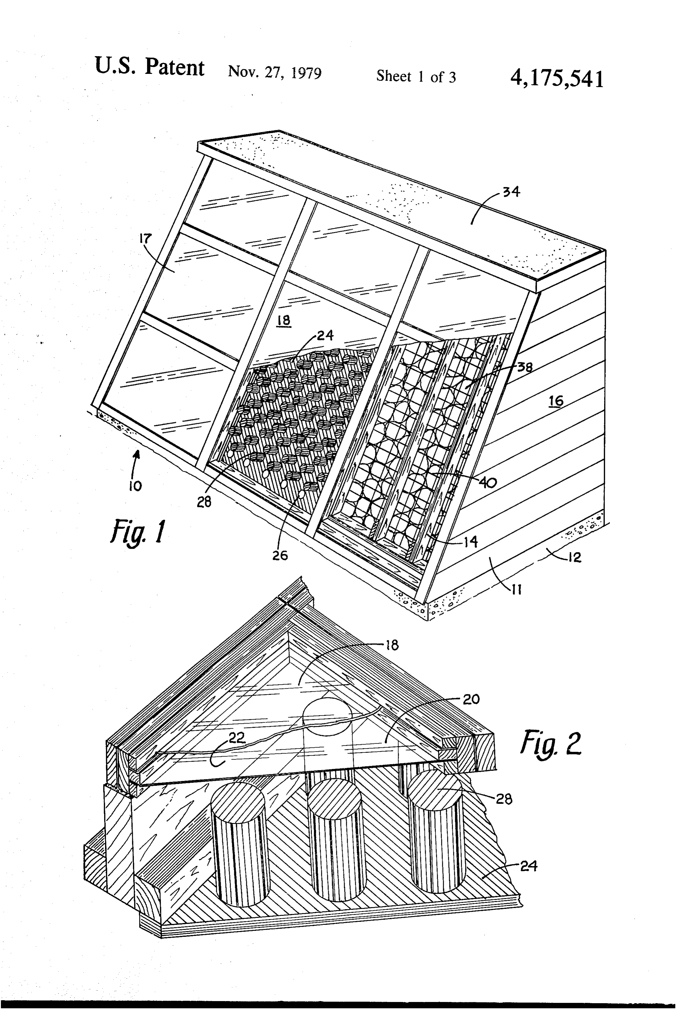
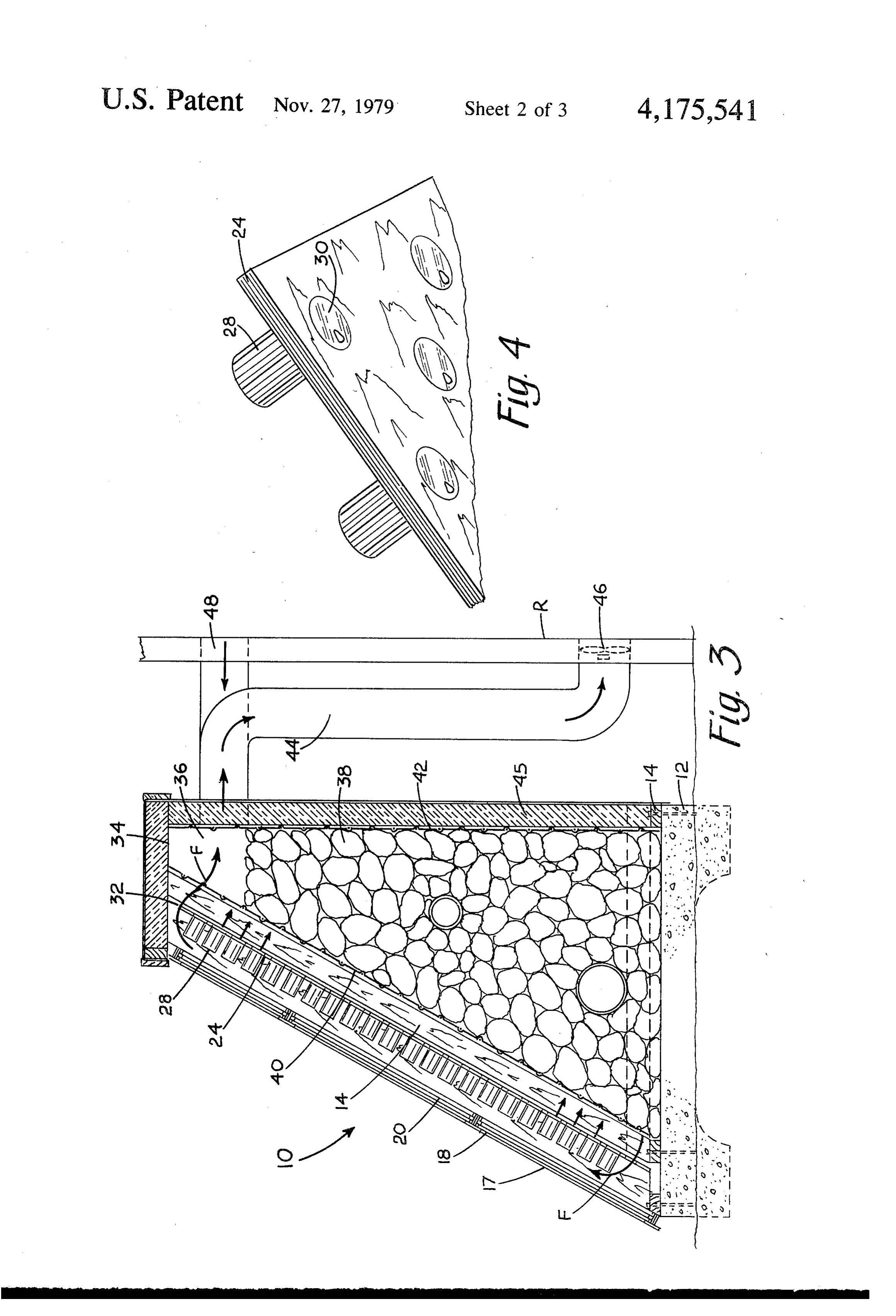
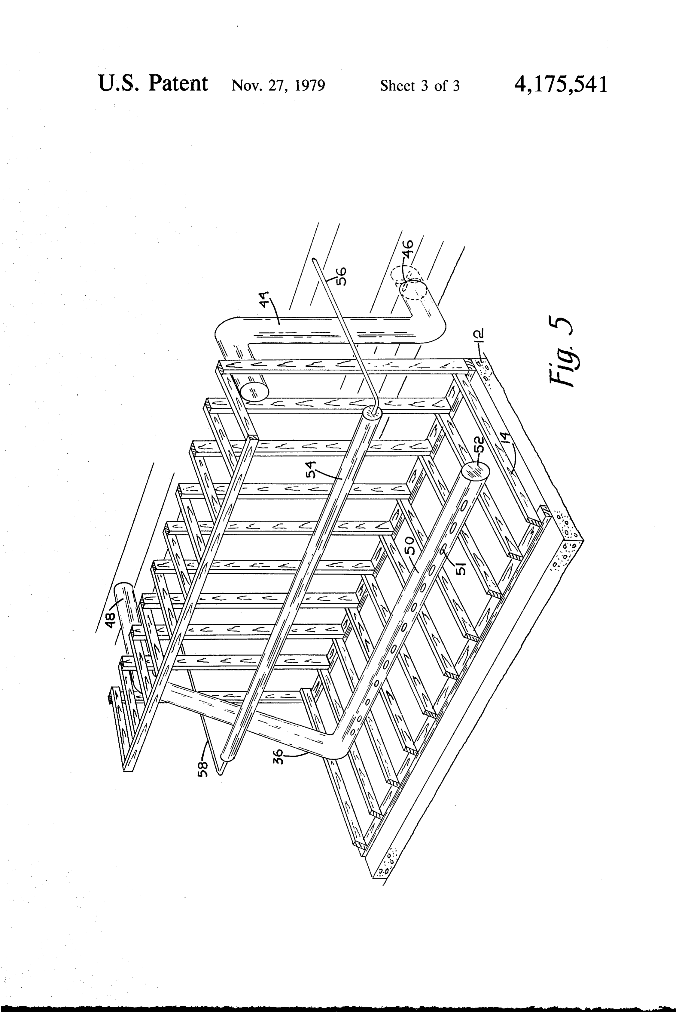
FIG. 2 is a partial isometric view of the solar collec
FIG. 3 is a section view of the system;
Page 2drawing sheetscan →
Page 3drawing sheetscan →
Page 4drawing sheetscan →
Page 5scan →
FIG. 2 is a partial isometric view of the solar collec
FIG. 3 is a section view of the system;
BACKGROUND OF THE INVENTION FIG. 4 is a partial isometric view of the underside of At the present time when sources of fuel are becom the collector panel; and ing more limited and costly, intensive efforts are being FIG. 5 is an isometric view of the framing and piping made to utilize solar energy as a heating medium. Sys embodying features of this invention. tems presently available enable conservation of fuel, but DESCRIPTION OF A PREFERRED the systems themselves have proven to be extremely 10 EMBODIMENT costly and generally constitute a major investment for Referring now to FIG. 1 with greater particularity, the building owner. the solar heating system 10 of this invention includes a OBJECTS OF THE INVENTION housing 11 on a foundation or slab 12 supporting fram ing 14 of suitable lumber, such as conventional 2X4's.
It is an object of this invention to provide a solar 15 Side panels 16 of wood or metal may be generally trape heating system which is relatively inexpensive to manu Zoidal in configuration to provide a front panel 17 facture. which slopes so as to be more nearly perpendicular to It is a further object of this invention to provide a the rays of the sun.
solar heating system which may be manufactured by the The front panel 17 comprises a double transparent homeowner from materials readily available. 20 wall made up of spaced parallel sheets 18 and 20 of glass It is a further object of this invention to provide a or a clear plastic, providing an insulating space 22 be solar heating system which is simple to manufacture and tween them. Hence the sun's rays may pass freely efficient in operation. through the glass panels 18 and 20 to heat a surface Other objects and advantages of this invention will upon which they impinge but, with the insulating space become apparent from the description to follow, partic 25 22 between the transparent sheets, the heat so generated ularly when read in conjunction with the accompany cannot move back out and is retained within the hous ing drawings. ing. Mounted behind the transparent panels 18 and 20, is
Summary of the invention
the collector panel 24 through which a multiplicity of circular holes 26 have been drilled. Fitted into most of
In carrying out this invention, there is provided an 30 the holes 26 are conventional beverage cans 28, so that enclosure with the front side angled to catch the sun's the tops of the cans 30 (FIG. 4) with pull tabs removed rays. The front panel has parallel sheets of a transparent are exposed through the collector panel 24. The ex material, such as glass or plastic, which enable the rays posed outer surface of the collector panel 24, as well as to pass but, having an insulating air space between them 35 the exposed outer surfaces of the cans 28 are coated resist outward transmission of heat. Just behind the with a dark paint to maximize their heat absorbing char transparent panels is a collector panel having a plurality acteristics, while the tops of the cans 30, are uncoated to of holes through it receiving a quantity of metallic cyl provide reflective radiating surfaces exposed through inders, such as beverage cans. The top with pull tab theItcollector will be panel 24.
noted that the bottom row of holes 26 are removed extends through the holes and the outer sur left open and the same may be repeated with one of the face of the collector panels as well as the outwardly top rows or, as shown in FIG. 3 the top edge 32 of the exposed surfaces of the upstanding cans are painted a collector panel may terminate short of the insulated dark, heat-absorbing paint, whereby the cans will ab ceiling 34. In any event, openings sorb heat and radiate it directly into a heat storage me top and bottom to enable circulationareofprovided at the dium, such as a pile of rocks disposed in a heat storage 45 between collector panel 24 and the front panel 17space air in the chamber at the other side of the collector panel. Open behind the collector panel 24 at the bottom to exit atfrom the ings at the bottom and top of the collector panel enable top as indicated by the arrows F.
natural circulation of air from the lower portion of the heat storage chamber through the bottom opening to ageDisposedchamber behind the collector panel 24 is a heat stor 36 in which a pile of heat absorbing stones the front of the collector panel, and then up over the 50 38 are confined between wire screens 40 and 42. It will collector panel to enterback into the heat storage cham be apparent that, in operation, relatively cool air is ber at the top. A hot air duct exits from the top of the drawn off at the bottom of the rock pile 38 to pass storage chamber and warm air is drawn through by a upward along the collector panel 24 and over and fan and projected in the room to be heated. Return air around the beverage cans 28 to be heated by the heat, enters each storage chamber at the same level that the 55 absorbent surfaces thereof and enter back into the heat heated air exits to that there is no natural circulation storing chamber 36 at the top. At the same time, the when the fan is not in operation. During circulation heated beverage cans 28 radiate heat directly into the return air is ducted downward to the bottom of the heat rockpile 38 from their metallic lids 30 greatly to elevate storage chamber where it is exited to be heated again. If the level of heat within the heat storage chamber 36. desired a water line may also extend across the heat 60 As seen most clearly in FIGS. 3 and 5 a hot air duct chamber at a slight incline to be heated and circulate 44 opens through the insulated rear panel 45 from near naturally. the top of the heat retaining chamber 36 to enter into BRIEF DESCRIPTION OF THE DRAWINGS the room R to be heated. A small fan 46 is provided in the heating duct 44 to deliver a stream of warm air from
In the drawings: 65 the solar heating system 10.
FIG. 1 is an isometric view partially broken away of A return duct 48 opens into the heat storage chamber a solar heating housing embodying features of this in 36 at the same level as the heating duct 44 exits, and vention; then as shown in FIG. 5, the return duct drops down to 6 the lower level of the heat storage chamber and then a plurality of hollow metallic cylinders in said open connects to an horizontal run 50 along the lower level ings with most of the lengths thereof extending of the heat storage chamber. Of course, horizontal run upward from said front side; 50 is of a more rugged construction and material to end closures on said cylinders on the end exposed withstand the load of rocks 38 disposed thereon. from said front side;
In operation, the fan 46 will draw warm air from the heat absorbing coatings on the outer surfaces of said top level of the heat storage chamber 36 to deliver it to end closures and exterior portions of said cylinders the room Rand the return air will enter through duct 38 exposed from said front side; ahd to exit through a series of openings 51 along the length 10 top closures with reflective surfaces on at least some of the pipe 50 for maximum distribution across the pile of said cylinders exposed through the back side of of rocks. Preferably the holes 51 are along both front said panel;
and back of the pipe 50, and the end 52 is capped. From wherein said panel is part of an enclosure and includ the lower level of the heat storage chamber 36 the air ing an accumulation of materials having heat re exiting through the holes 51 is again circulated to the 15 taining characteristics in said inclosure rearward of heating system as above described. Since the return the back side of said panel; - whereby, said cylinders radiate heat directly to said duct 48 enters the heat storage chamber 36 at the same materials.
level as the heating duct 44, there will be no circulation 2. The solar heating system defined by claim 1 includ of air and, hence, no heating of the room R when the fan ling:
is turned off. 20 through openings at the top and bottom of said panel Also if desired, the heating system 10 of this invention to enable flow of cooler air from said back side to may be used to heat water and, for this purpose, a rela the front side of the bottom to flow upward across tively large pipe 54 slopes upwardly from right to left in said front side and said cylinders and then, after FIG. 5 with smaller cold 56 and hot 58 water pipes being warmed, flow to the back side of the top of being connected at the ends. Again, with the pipe 54 25 said panel.
sloping upwardly the water is heated by the rocks 38 3. The solar heating system defined by claim 1 includ and the warmer water rises naturally to circulate out at 1ng:
58. a pair of parallel transparent sheets spaced generally While this invention has been described in conjunc parallel to and above the front side of said panel to tion with a preferred embodiment thereof, it is obvious 30 enable passage of solar rays but with an air space that modifications and changes therein may be made by between them to insulate against outward passage those skilled in the art without departing from the spirit of heat.
and scope of this invention as defined by the claims 4. The solar heating system defined by claim 1 includ appended hereto. 1ng:
Having described my invention, I claim: 35 a heating duct from the top of said enclosure to the 1. A solar heating system comprising: lower portion on of a room being heated; and a collector panel having a frontside adapted for expo a return duct from the upper portion of said room sure to solar radiation and a back side; being heated to the upper portion of said enclosure a heat absorbing coating on said front side; at the level of said heating duct. a plurality of circular openings through said panels; 40 -
Provenance
- Collection
- Patents citing this work
- Pages
- 6
- Method
- pdftotext (the PDF's own text layer) + pdftoppm 300dpi page scans
- Patent office record
- patents.google.com →
- Source
- Google Patents citing-documents table
- Assignee
- Midgley Calvert H
- Published
- 1979-11-27
- Transcribed from
- patentimages.storage.googleapis.com →