

patent · US4056092A
Flat plate solar energy collector
1 November 1977
Text
Page 1scan →
United States Patent (19)
Meier et al.
(54) flat platesolar energy collector
76 Inventors: Harold K. Meier; John Michael
Popovich, both of 9620 Royalton
Drive, Beverly Hills, Calif. 90210
51) Int. C.’................................................. F24J 3/02 52 U.S.C. ..................................... 126/271; 165/170
705,350 7/1902 Hubert ................................. 26/271 1,889,238 11/1932 Clark ...... ... 126/27 1969,839 8/1934 Goddard .... ... 126/271 3,107,052 0/1963 Garrison ... ... 126/271 3,146,774 9/1964 Yellott .................................. 126/271 3,277,884 10/1966 Rowekamp. ... 126/271 3,399,664 9/1968 Suhay ............. ... 126/271 3,561,425 2/1971 Gardner ............. ... 126/27 3,620,206 11/1971 Harris, Jr. et al...... ... 126/271 3,799,145 3/1974 Butterfield ..... ... 126/271 3,943,911 3/1976 Yu ........................................ 126/271
Foreign patent documents
272,027 1/1963 Canada ................................. 126/27
Primary Examiner-Kenneth W. Sprague
Assistant Examiner-James C. Yeung
Attorney, Agent, or Firm-Lyon & Lyon
An improved form of flat plate collector of the type used for heating a fluid, such as water, using solar en ergy. The structure comprises a cast or molded body having a surface which is absorptive to solar radiation, above which is positioned a sheet of material transpar ent to solar radiation forming a flat hollow cavity through which a thin sheet of water is passed in contact both with the transparent material and the absorptive surface. The thin sheet of water acts both as a means for transferring energy from source to sink and as an inter ference filter as well. The cast body may also incorpo rate suitable plumbing passages and means for intercon necting a plurality of collector modules.
9 Claims, 3 Drawing Figures
Drawings
Page 2drawing sheetscan →
Page 3scan →
is essentially transparent and somewhat absorptive to
FLAT PLATESOLAR ENERGY COLLECTOR incoming solar radiation, but substantially opaque to energy reradiated from the absorptive surface. The
BACKGROUND OF THE INVENTION collector is formed with a flat surface having peripheral Mechanisms for harnessing and utilizing the Sun's 5 walls with a sheet of transparent material sealingly en energy have taken many forms and one such mechanism closing an interior space having a thin flat configuration has come to be known as a flat plate collector. In such in which water is circulated. A number of projections a device, a planar structure is provided with a surface extending from the absorber surface support the trans which is absorptive to the solar energy and which con parent sheet. Water to be heated is passed through the verts that energy to heat, and then fluid is circulated 10 collector between the absorber surface and the trans over or in conductive contact with that surface to ab parent sheet and in direct contact with the inner sur sorb the heat from the surface area whereupon the fluid faces of both of them. The transparent sheet may also is conducted away carrying the energy with it. The possess interference filter characteristics and, when energy contained in the heated fluid has many end uses used together with the thin sheet of water, provides a as a heat source, the end uses not being the subject of 15 collector of enhanced efficiency.
Description of the drawings
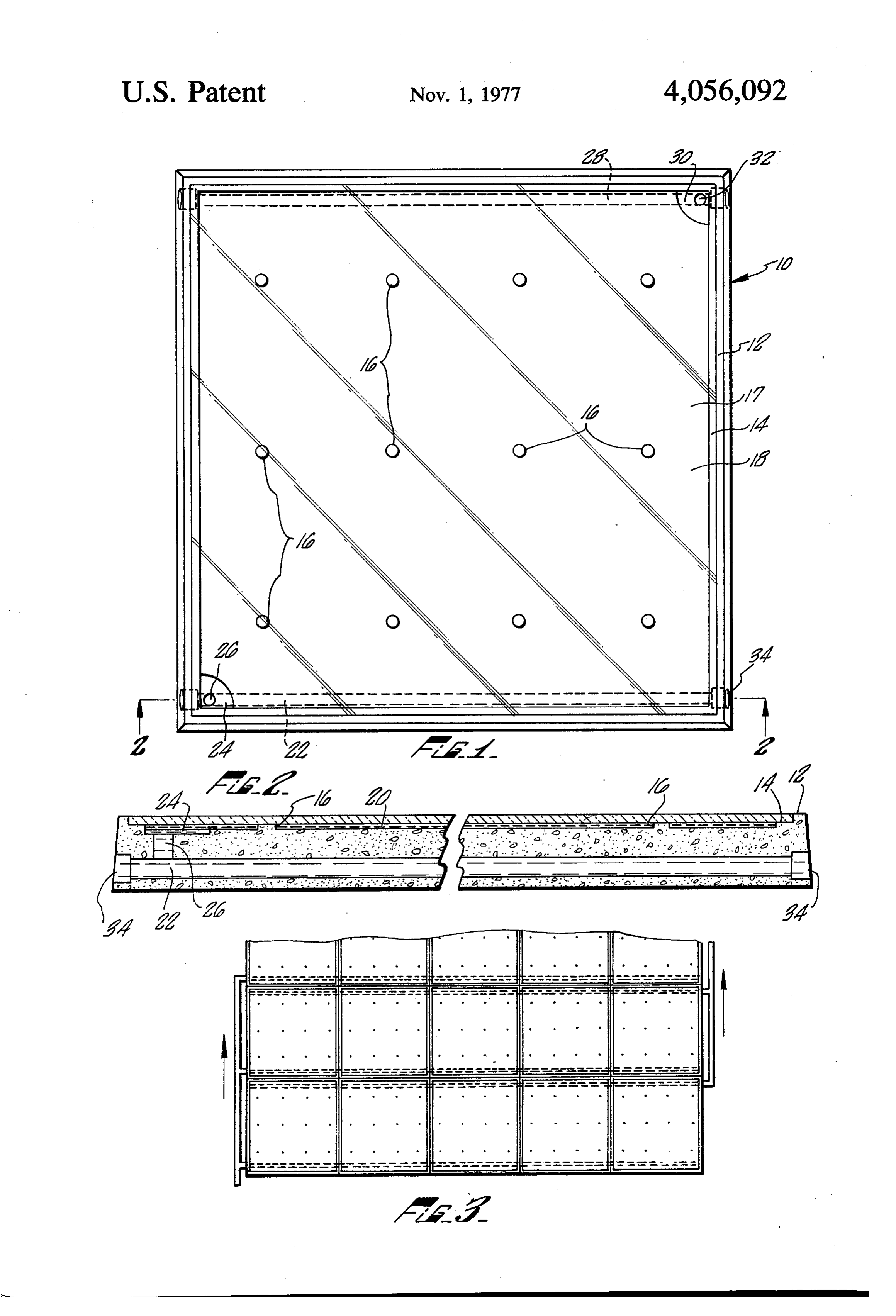
The most common features of flat plate collectors heretofore known include water flowing through cop FIG. 1 is a plan view of a flat plate collector module per tubing in an insulated enclosure. The surfaces of the made in accordance with the present invention. copper tubing are provided with energy absorptive 20 FIG. 2 is a sectional side elevation taken along Line coatings, or other energy absorptive surfaces are pro 2-2 of FIG. 1.
vided in contact with the copper tubing so as to absorb FIG. 3 is a plan view showing a plurality of collector the solar energy converting it to heat and conducting modules coupled together in parallel. the heat to the water. A glass or other transparent cover DESCRIPTION OF THE PREFERRED is provided minimizing convection losses and, at the 25 EMBODIMENT same time, creating a "greehouse effect' thereby reduc ing reradiation losses from the system. A collector module has a base 10 consisting of a gen It is known that the wavelength of energy radiated erally flat rectangular member preferably cast or from a heated body is inversely proportional to the molded. The base material may also contain lightweight temperature of that body. The spectrum of solar energy 30 aggregates and other additives to reduce the weight of reaching the earth's surface is comprised substantially the structure or provide other properties, such as heat of wavelengths in the range of approximately 0.3 to 3.0 insulation depending upon the specific use intended. microns. The energy radiated from an absorptive sur Thus, one could select from a number of compositions face having a temperature of 40 C is composed of which can be cast or molded, are heat insulative, struc wavelengths between 8.0 and 10.0 microns. Thus, it is 35 turally strong, lightweight and capable of withstanding apparent that by providing a material which is transpar exposure to the elements including elevated tempera ent or absorptive to the incoming radiation having the tures of about 100° C or even higher. The base 10 incor short wavelengths and opaque or absorptive to the porates an integral peripheral wall 12 having an inner energy radiated from the absorptive surface having shoulder 14 and a plurality of integral support members longer wavelengths would greatly increase collector 40 16 projecting from the flat absorber surface 17. The efficiency. Such materials are available and known ge support members 16 are stationed at spaced intervals as nerically as interference filters. Some glass and some necessary. A sheet of transparent material 18 rests upon plastics have these characteristics and are commonly the peripheral shoulder 14 and is sealingly adhered used in flat plate collectors. thereto and to the peripheral walls 12. Transparent The principal shortcoming of prior flat plate collec- 45 sheet 18 likewise rests upon the support members 16 and tors has been their complexity and use of expensive may be adhered thereto if desired. Supports 16 are com materials such that such devices have been unable to posed of the same material as base 10, being integral compete with fossil fuels in the energy market. Al therewith, and are not intended to be heat conductive. though inexpensive to operate, their high initial cost, The transparent sheet 18 is thus supported by the pe including installation costs, has made them noncompeti- 50 ripheral shoulder 14 and the projecting support mem tive. . . ." bers 16 to provide a thin flat cavity 20 of substantially SUMMARY OF THE INVENTION uniform cross section. The thickness of the cavity 20 is approximately 0.125 inch but may be varied within
The principal advantages and objects of the present limits. The lower limit is not always the same, but de invention include an extremely low initial cost as well as 55 pends upon flow rate, temperature of incoming water, a light weight and high structural strength such that the desired temperature increase, etc.; except that too thin a collectors can be utilized as structural building compo cavity will provide a layer of water which will not have nents. The low cost of collectors made in accordance sufficient interference filtering capabilities at operating with the present invention is the product of the use of temperatures. The upper limit of the cavity thickness is inexpensive materials combined with a simple design 60 also a determinative factor in the amount of heat trans that is easy to manufacture. Low cost is also the result ferred to the water flowing therein, but the same other of the ability to use such collectors as building compo factors are also determinative, including the flow rate, nents thereby further reducing overall building costs. etc. The optimum limits for the cavity thickness are yet The present invention obtains the foregoing objects to be determined and will vary depending on water and advantages as the result of its unique configuration 65 chemistry, absorptive characteristics of the surface 17, which permits the utilization of the water itself as an flow rate, desired temperature increase and other fac interference filter. Applicants have found that a thin flat tors. Suffice it to say that by "thin' it is meant that the sheet of water of the proper thickness and configuration cavity-thickness is on the order of 0.125 to 0.250 inch.
Page 4scan →
The uniformity of thickness is an important factor wise require reinforcement in such cases. The advan which affects the spectral filtering characteristics of the tage of the present invention is that the panels them water in this cavity. selves are structurally strong and, since only a small The base 10 also has cast therein a fluid inlet conduit amount of water is in a collector plate at any one time, 22, an inlet reservoir 24 coupled to the inlet conduit 22 further reinforcement is not necessary in most instances. by riser 26. The body 10 likewise includes an outlet As previously stated, the transparent sheet may be glass conduit 28 coupled to an outlet reservoir 30 by a riser or other plastics which have interference filter charac 32. teristics. The utilization of glazing material having such The absorber surface 17 is made spectrally absorptive characteristics further increases the efficiency of the either by the incorporation of additives in the casting O collector plate by further reduction of reradiation material or by applying suitable coatings to this surface. losses.
Such coatings are generally known to the art. The inlet While that has been described herein is a particular and outlet conduits 22 and 28 are supplied with enlarged configuration and embodiment of the present invention, bores 34 or other similar coupling means as desired so it will be apparent to those skilled in the art that changes that individual collector modules of the approximate 15 and modifications might be made therein while still configuration of that shown in FIG. 1 may be intercon employing the basic concepts of the present invention, nected, as shown in FIG. 3. Similarly, for collector and it is recognized that many such changes and modifi modules designed for coupling together to form a larger cations might be made without departing from this collector panels, the side walls on all sides are sloped invention in its broader aspects.
slightly, as can be seen in FIG. 2, a few degrees from the 20 We claim:
vertical so that individual modules can be readily sta 1. A solar energy collector comprising: tioned in side-by-side relationship and interconnected a first member defining a first planar surface, said without interference one with the other. planar surface being spectrally transparent to solar As shown in FIG. 3, a number of collector modules radiation;
are coupled together and may be connected for fluid 25 a second member defining a second planar surface transmission by inserting a small tube or other connec parallel to and spaced from said first planar surface, said tor means in the bores 34 of conduits 22 and 28 so that second planar surface being spectrally absorptive to the collectors are connected in parallel, that is all outlet solar radiation;
conduits are connected to one another and all inlet means adhering said first and second members to conduits are connected to one another. Other suitable 30 gether in a fluid-tight relationship defining a cavity means for interconnecting the inlet and outlet conduits between said first and second planar surfaces, said may be used according to techniques well-known in the cavity having a cross-sectional dimension of about art. By so coupling a plurality of collector modules to inch; and together, a large collector assembly may be constructed means for continuously circulating fluid through said of virtually any size and configuration. It should also be 35 cavity to define a radiation interference filter spec understood that the peripheral configuration of the trally transparent to solar radiation and spectrally individual collector module is not necessarily limited to opaque to heat radiation.
a square or rectangle but the casting process permits 2. The combination of claim 1 wherein said cross-sec many shapes to be employed so that collector assem tional dimension is about of an inch. blies using a number of such panels may be assembled 3. The combination of claim 1 wherein said first pla having any desired configuration. nar surface is glass which is spectrally transparent to In some cases, it is not necessary to pump water solar radiation and spectrally opaque to heat radiation through the collectors and, therefore, additional energy coming from said second planar surface. is not necessary for that purpose as the water will circu 4. The combination of claim 1 wherein said first pla late through the collector plates by the thermo-syphon 45 nar surface is spectrally to both solar radiation and heat principle; that is, the collector plate is situated at an radiation.
inclined angle with the inlet conduit along the lower 5. The combination of claim 1 wherein said circulat edge. Cool water introduced along the lower edge is ing means comprises conduit means integrally formed heated and rises circulating it upwardly wherein it will within said second member and communicating with exit at the top. 50 said cavity for induction and eduction of fluid. In operation, direct and diffused solar radiation passes 6. A solar energy collector comprising: through the transparent layer and then through the enclosure means defining a cavity having a thin flat uniform layer of water impinging upon the absorptive configuration, said cavity being fluid tight and hav surface 17. There, the energy is converted into heat. ing conduit means coupled thereto for induction Water in contact with the absorptive surface thereby 55 and eduction of fluid;
receives heat transferred to it. The layer of water acts as a first element of said enclosure comprising a planar an interference filter in the manner previously described sheet of material transparent to solar radiation, said in that it is substantially opaque to the heat energy rera first element defining one side of said cavity; and diated from the absorptive surface and such reradiated a second element of said enclosure defining the side of energy is thereby captured because of the filtering ef 60 said cavity opposite said transparent sheet and par fect and not radiated back to space but rather is con allel thereto, said second element having a planar ducted and radiated to the water. The uniform layer of surface on the interior of said cavity, said planar water thus acts as its own interference filter and, in surface being spectrally absorptive to solar radia addition, reduces the weight of the overall structure tion and spaced from said first element a distance of which may be important, if such panels are installed as 65 about 1/8 inch to 1/4 inch such that upon circulat roofing material or as other structural components. It is ing a fluid within said cavity from said induction to not desirable to have a large quantity of water circulat said eduction means in physical contact with both ing on a roof as water is quite heavy and would other the interior surfaces of said first and second ele 5 ments a radiation interference filter spectrally trans 8. The solar energy collector set forth in claim 6 parent to solar radiation and spectrally opaque to wherein said first planar element comprises glass which heat radiation is defined.
is spectrally transparent to solar radiation and spectrally 7. The solar energy collector set forth in claim 6 opaque to heat radiation coming from the interior sur face of said second planar element.
including spacer means positioned within said cavity 9. The solar energy collector set forth in claim 6 between said first and second planar elements, said wherein said first planar element is spectrally transpar spacer means maintaining said first and second elements ent to both solar radiation and heat radiation.
in substantially parallel relationship.
Provenance
- Collection
- Patents citing this work
- Pages
- 5
- Method
- pdftotext (the PDF's own text layer) + pdftoppm 300dpi page scans
- Patent office record
- patents.google.com →
- Source
- Google Patents citing-documents table
- Assignee
- Meier Harold K
- Published
- 1977-11-01
- Transcribed from
- patentimages.storage.googleapis.com →