

patent · US4120285A
Modular tubular solar energy collector apparatus
17 October 1978
Text
Page 1scan →
United States Patent (19)
Nugent
54 modulartubular solar energy
Collector apparatus
75 Inventor: Duane C. Nugent, Perrysburg, Ohio 73) Assignee: Owens-Illinois, Inc., Toledo, Ohio (51) Int. C. ................................................. F24J 3/02 52 U.S. Cl. ..................................... 126/271; 126/270
980,505 1/1911 Emmet ................................. 126/271 1,068,650 7/1913 Harrison .... ... 126/271 1,575,309 3/1926 Anderson ... ... 126/271 1,683,266 9/1928 Shipman ..... ... 126/27 1,696,003 12/1928 Harvey ....... ... 126/271 1,880,938 10/1932 Emmet ... ... 126/270 1,946, 184 2/1934 Abbot ..... ... 126/271 1,951,403 3/1934 Goddard . ... 126/271 1989,999 2/1935 Niederle. ... 126/271 2,133,649 10/1938 Abbot ................................... 126/271 2,141,330 12/1938 Abbot ..... ... 126/271 X 2,205,378 6/1940 Abbot ................................... 126/271 2,213,894 9/1940 Barry .................................... 126/271 2,247,830 7/1941 Abbot. ... 126/271 2,460,482 1/1949 Abbot ..... ... 126/271 2,872,915 2/1959 Bowen .... ... 126/271 2,917,817 12/1959 Tabor ..................................... 29/180 3,227,153 1/1966 Godel et al. ... ... 126/271 3,853,114 12/1914 Taydos....... ... 126/271 3,952,724 4/1976 Pei........... 165/142 X 3,960, 136 6/1976 Moan et al. . ... 126/271 4,002,160 1/1977 Mather, Jr. . ... 126/271 4,016,860 4/1977 Moan ...... ... 126/270 4,018,215 4/1977 Pei........................................ 126/270 4,027,653 6/1977 Meckler .. ... 126/270 X 4,030,477 6/1977 Smith ................................... 126/270 4,033,327 7/1977 Pei........................................ 165/142 4,043,318 8/1977 Pei.................................... 165/166 X
Foreign patent documents
Other publications
H. Tabor, "Selective Radiation, I Wavelength Discrim ination Bulletin of the Research Council of Isreal,' ,
H. Tabor, J. Harris, H. Weinberger and B. Doron,
"Further Studies on Selective Block Coatings,' United
Nations Conference on New Sources on Energy, Apr.
Primary Examiner-William F. O'Dea
Assistant Examiner-Larry Jones
Attorney, Agent, or Firm-John R. Nelson; Myron E.
Click; David H. Wilson
The disclosure relates to a modular form of solar energy collector apparatus in which several double-wall glass tube collectors, each with vacuum jacket, depend from opposite sides of an elongated manifold. The manifold includes split halves of foamed polymer insulation and rigid fiberglass reinforced skin thereon, assembled about closed-looped, serpentine liquid carrying tubes preferably of metal or glass in U-tube configurations depending from the manifold halves and extending into the larger double-walled glass tubes, the serpentine tube being connected, respectively, into inlet and outlet header pipes. The interior chamber of the collector tubes is closed by the manifold, thereby enclosing a part of each U-tube branch of the serpentine in a non-turbu lent air space. Solar energy collected on the absorber surface of the inner glass tube wall is transmitted to the U-tube and liquid therein. The U-tube within the collec tors is blackened and non-reflecting. Principal heat transfer from absorber to U-tube is by radiation with some conduction and convection transfer. The heat transfer liquid is entirely within a closed circuit, which avoids leaks, reduces weight, and cycle time of the liquid is reduced to a fraction of other liquid systems.
The manifold and tubes are fastened to a support struc ture of novel construction enabling fabrication as a module and mounting on a solar exposure of a structure such as a roof, wall or frame. Several modules are inter connectable to desired capacity for a particular solar powered heating or cooling system.
41 Claims, 12 Drawing Figures
Drawings
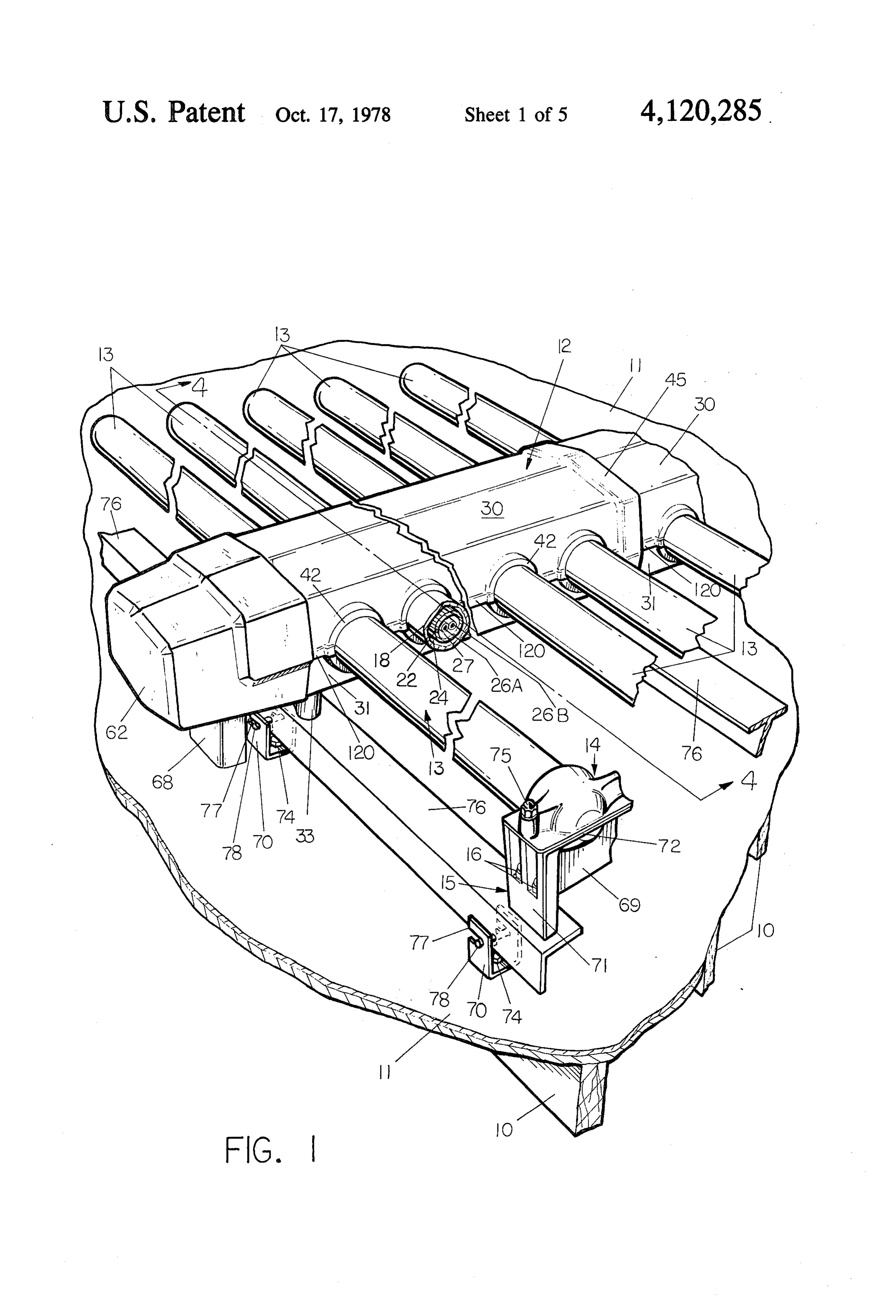
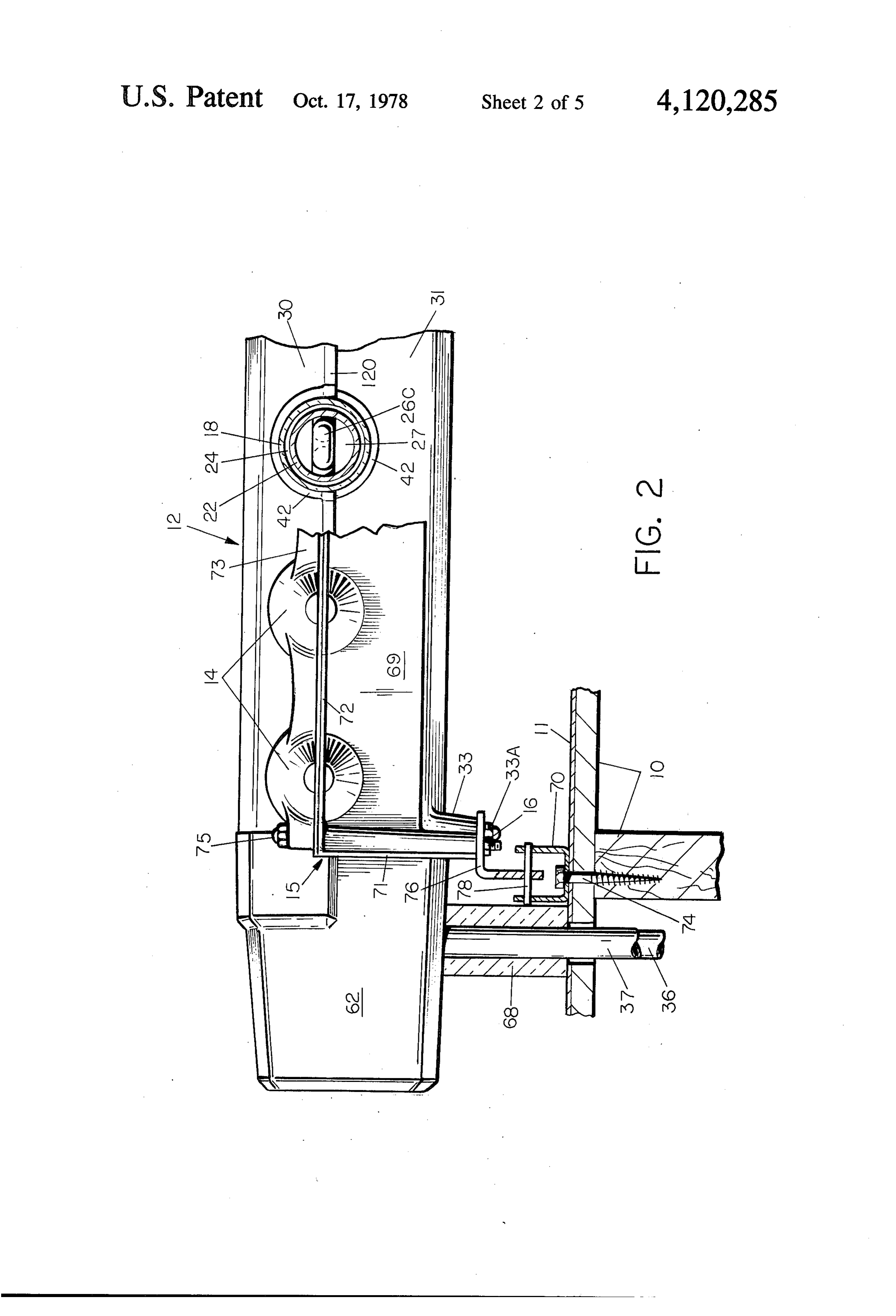
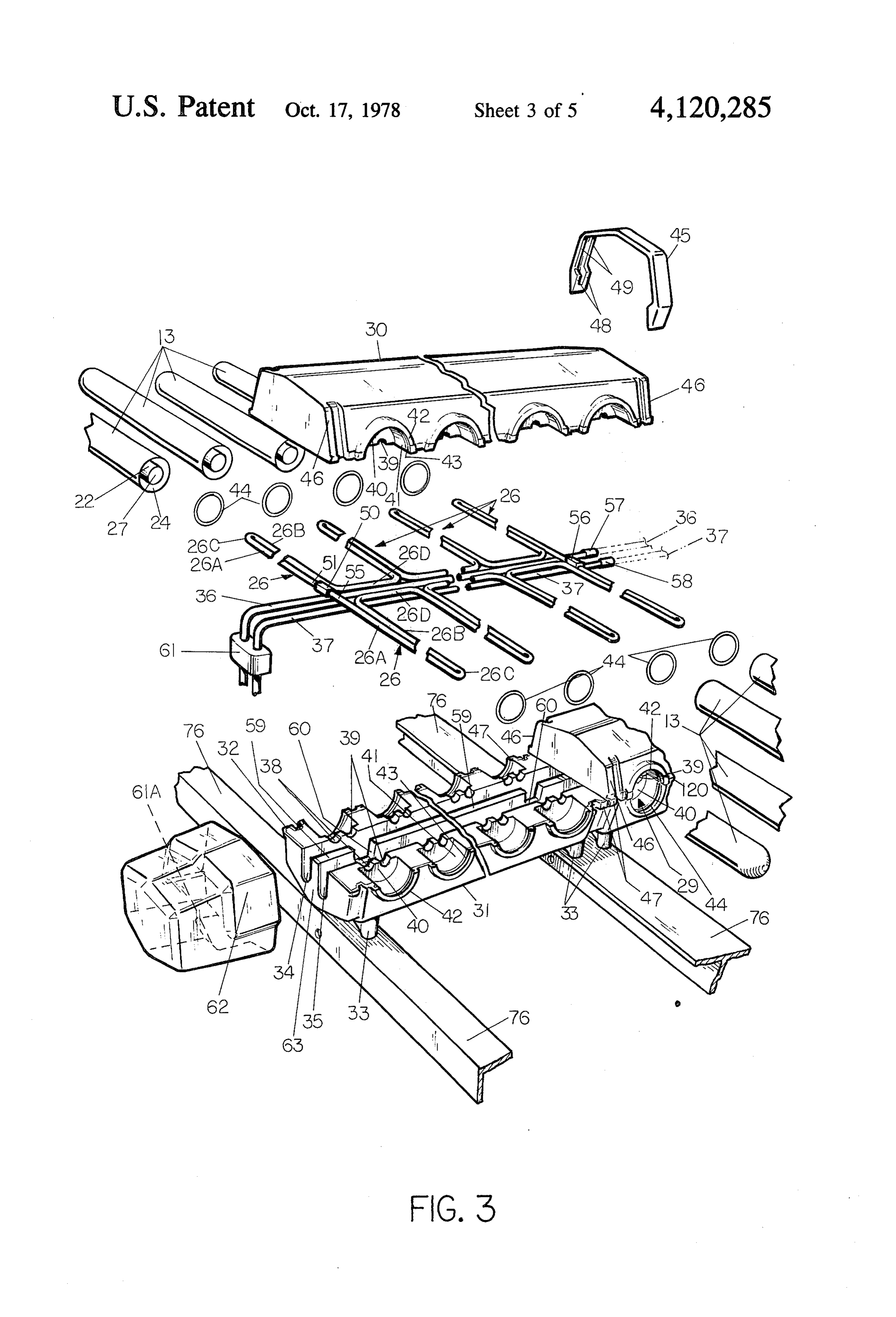
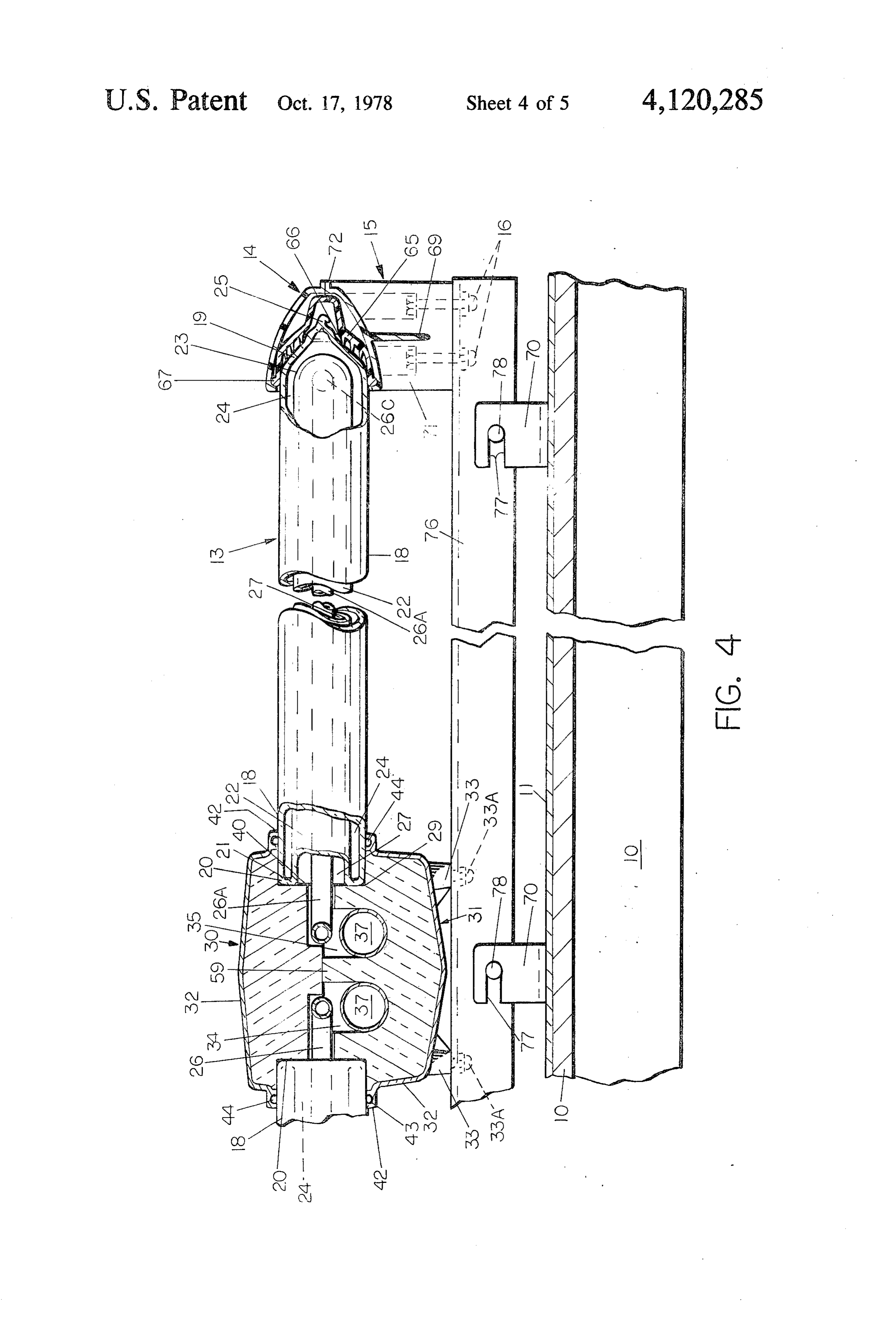
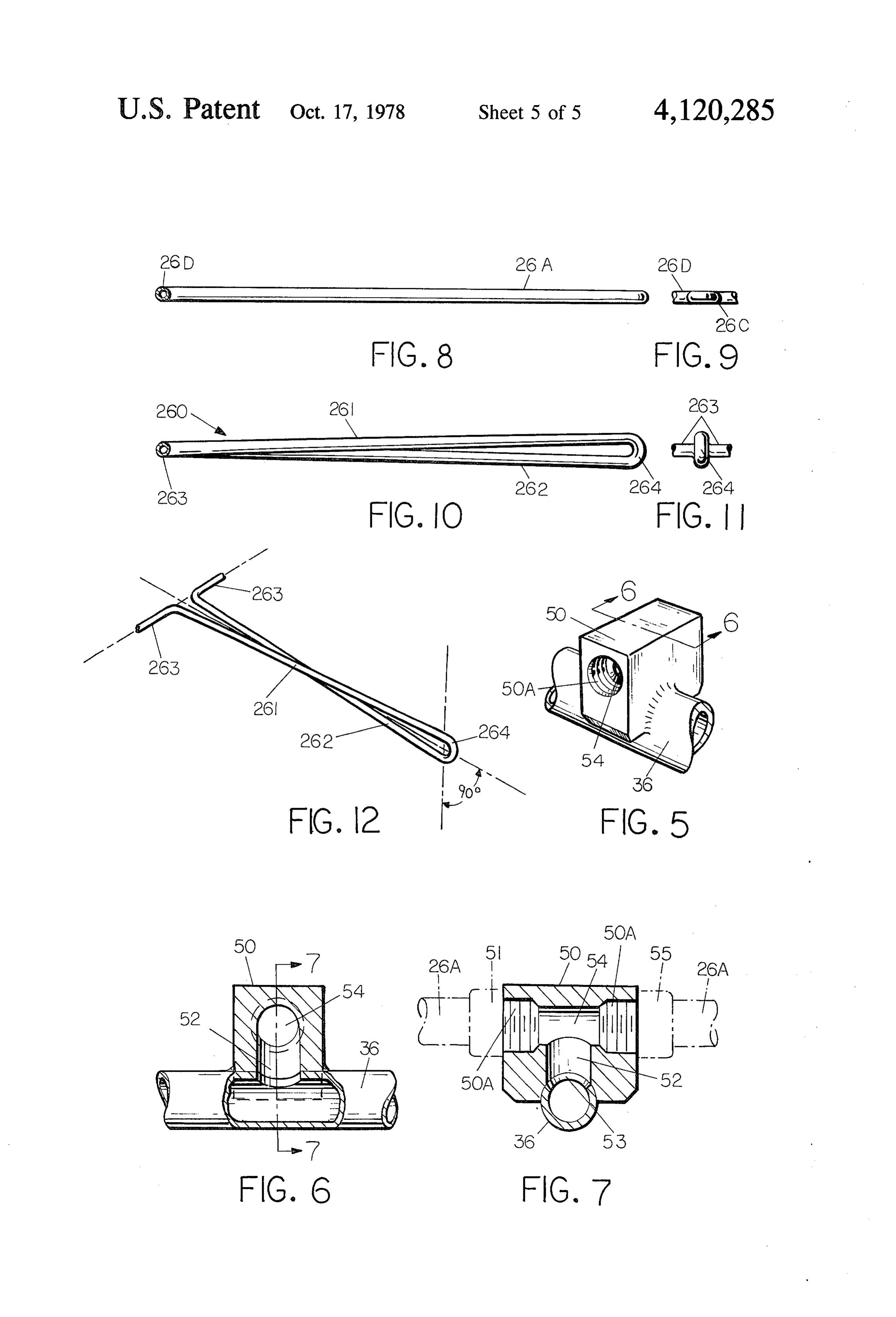
FIG. 1 illustrates an example of the solar energy transfer media selected for its properties in transfer of apparatus module installed on a frame support surface heat from the glass absorber tube wall to the surface of 10, such as the roof or a solar exposed wall of a building. the U-tube 26. Air is a suitable example of such gaseous The surface 10 should be located with best exposure to media.
Page 2drawing sheetscan →
Page 3drawing sheetscan →
Page 4drawing sheetscan →
Page 5drawing sheetscan →
Page 6drawing sheetscan →
Page 7scan →
tubular collector is connected at its open end onto the
MODULARTUBULAR SOLAR ENERGY manifold such that the interior chamber of the absorber COLLECTORAPPARATUS tube in the collector is closed, such as by means of the manifold matrix. The liquid circulation system com
The present invention relates to apparatus for collec prised of the U-tubing resides in a stagnant, or non-tur tion of solar radiation energy and transmittal of that bulent air spaced inside the collector and the radiant energy as heat in a liquid media for purposes of utiliza solar energy absorbed on the coating of the inner wall tion in an energy consumption system. of the collector is transmitted as heat through radiation, BACKGROUND OF THE INVENTION conduction and natural convection transfer to the U
Efficient collectors of tubular variety are disclosed in tube and the liquid circulated therein. The invention also includes a split manifold member
U.S. Pat. No. 3,952,724 and commonly owned, copend formed of a low density insulation body and a dense, ing application Ser. No. 634,714 filed Nov. 24, 1975 non-porous and durable exterior skin. The manifold (now U.S. Pat. No. 4,033,327), both setting forth inven member supports and encloses the liquid closed circuit tions of Y. K. Pei in modern, advanced solar collector 15 connected as a serpentine of tubing including several design. The prior collectors just referred to utilize, for U-tubes in collectors and closure for the open end of the the most part, a liquid media to absorb and transmit collector tubes. The serpentine tubing is connected to energy as heat collected on a tubular solar absorbing an internal, enclosed header pipe circuit for handling surface of a collector. The liquid is handled in a mani the incoming and outgoing liquid in the system. The fold for series flow distribution thereof into the interior 20 chamber of a series of absorber tubes. To maintain the manifold in the preferred embodiment herein disclosed circuit leakproof, the collectors are sealed in the mani as includes integral support and mounting standards made fold and end pressure on the tube is provided in the mounting a part of the durable exterior skin covering for structural support to bias the internal liquid pressure in the apparatus.
the interior chamber of the absorber tube as arise at 25 A further feature of the invention includes the modu operating temperatures of the system. The collectors lar mounting of the collectors on a frame incorporating are constructed from glass tubing components and have into a modular unit the necessary elements of the collec an annular vacuum jacket between the outside tube wall tor, manifold (including the closed tubing circuit), re and the inside, absorber tube wall. The liquid is freely flector means and supports. The modular construction introduced from the manifold into the absorber tube 30 provided by the invention enables ground erection of a interior by a delivery tube circuit from which the liquid single module or in series grouping of modules on a flows within the confines of the absorber tube body to framework ready for hoisting to the place of installation the manifold. Breakage of the tubular collector, and in at a desired solar exposure. Installations are most preva particular, breakage of the absorber tube; or unseating lent atop of buildings or at elevated locations, and the and leakage of one of the collector tubes from the mani 35 ease of installation offered by the invention enhances fold causes leakage or spillage of liquid and a resulting erection and reliability of the installation. malfunction, or, at best, loss of efficient operation of one Since the liquid is completely contained in tubing, module segment of the system. hydrostatic testing may be performed as part of the
Summary of the invention
installation procedure to assure a leak free system. This will be maintained until a tubing rupture occurs. Ac
The object of the invention is to provide an improved cordingly, the invention provides improved safety and advanced solar collection system in which a liquid heat maintenance advantages. If a glass collector tube is exchange media is completely contained and circulated broken in service, it can be replaced without interrupt in a closed tubing circuit to and through the tubular ing flow of the liquid or without any loss or spillage of glass collectors. 45 the liquids; i.e. the system need not be shut down. The In the invention, an important aspect is the elimina only loss in the system should a tube be broken would tion of water tight seals on the end of the collector tube be a performance efficiency drop proportionate to the in the manifold without loss of fluid should leakage or tube or tubes out of service.
breakage or the collector tube occur. Also, the system is As will be apparent, other objects and advantages capable of much higher operating pressure and temper 50 will undoubtedly occur to persons skilled in the art ature operation. from the following description and the accompanying Another important feature of the invention is in the drawings.
reduction of weight when filled and a lower time con BRIEF DESCRIPTION OF THE DRAWINGS stant for liquid cycle circulation. The shorter time con stant for the liquid cycle benefits the control over the 55 FIG. 1 is a perspective view, partly broken away, of heat collection output of the collector. the modular unit of improved solar energy collectors of The basic structure of the collector tube of the inven the invention;
tion consists in an elongated, double-walled glass tube FIG. 2 is a side elevational view, partly broken away, that is closed at the one outer end and is open at the showing the modular unit of collectors of FIG. 1 in other end. The surface of the inner wall of the tube is 60 stalled on the structural modular frame installed at a site covered with an absorption coating, preferably a wave exposed to solar radiation.
length selective coating having the properties of high FIG. 3 is an exploded perspective view, in part, of absorption and low emissivity. The walls are separated one modular unit of the apparatus of the invention; by an annular vacuum chamber to reduce conduction FIG. 4 is a sectional end elevational view taken along and convection loss. The liquid is completely contained 65 line 4-4 on FIG. 1;
in manifold and U-tubing as part of the closed circuit FIG. 5 is an enlarged perspective view of the connec and the U-tube portion is inserted into the interior tor for the serpentine formation of tubing and one of the chamber of the absorber tube wall of the collector. The manifold header pipes;
Page 8scan →
FIG. 6 is a side elevational view, partly in section, of in the commonly owned, copending application Ser. the connector taken along line 6-6 on FIG. 5; No. 695,538, filed June 14, 1976. The O.D. of tube 22 is, FIG. 7 is a sectional view of the connector taken for example, on the order of 2 inches. Preferably, this along line 7-7 on FIG. 6; absorbing coating layer is on the exterior surface of the FIG. 8 is a side elevational view of the liquid U-tube 5 glass absorber tube 22 which has a curved, closed end portion of the serpentine tubing formation according to 23. The space 24 between tubes 18 and 22 is evacuated the first embodiment of the invention; through an end tubulation 25 to a hard vacuum and FIG. 9 is an end view of the U-tube shown on FIG. shown tipped off in conventional manner after the vac 8; uum is drawn. The vacuum in the space 24 eliminates FIG. 10 is a side elevational view of a liquid U-tube 10 convection and conduction heat loss of solar energy conduit illustrating a further embodiment of the inven that is absorbed on the coating surface of tube 22. tion in which the U-tube is twisted to lie in a plane near To convey the energy absorbed on tube 22 as heat its one end that is disposed 90 degrees in relation to the from the collector element and into use in a system to plane at its other end; which the collector apparatus may be incorporated, the FIG. 11 is an end view of the U-tube shown on FIG. 15 invention employs a bent, elongated U-tube 26 of rela 10; and tively small OD (on the order of or inch diameter) FIG. 12 is a perspective view of the twisted U-tube which is inserted inside the larger diameter internal embodiment shown on FIGS. 10 and 11. chamber 27 of absorber tube 22 (I.D. of about 1.
Description
inches). The remaining area inside chamber 27 is a dead 20 air space, or may be filled with any other gaseous heat
FIG. 1 illustrates an example of the solar energy transfer media selected for its properties in transfer of apparatus module installed on a frame support surface heat from the glass absorber tube wall to the surface of 10, such as the roof or a solar exposed wall of a building. the U-tube 26. Air is a suitable example of such gaseous The surface 10 should be located with best exposure to media.
the sun, such as a southern exposure in the Northern 25 The U-tube 26 is preferably of ductile material which Hemisphere, etc. is preferably capable of withstanding high pressure and A planar diffuse reflector 11 is positioned on top of high temperature operating conditions and which may the framework 10 and the solar collector module is be readily bent to a rather sharp reverse bend 26C pre mounted over the support 10 and reflector surface 11 scribing the one longitudinal extremity of tube 26. From and spaced above the upper surface of the latter a pre 30 the bend at the one end 26C, the two elongated side-by scribed amount to enhance diffuse reflection of the sun's side reaches 26A and 26B of the tubing extend to the rays. The planar reflector 11 is like that disclosed in open end of the absorber tube outside the end of the commonly owned, copending application Ser. No. double-walled tubular collector element 13. Depending 549,291, filed Feb. 12, 1975; now U.S. Pat. No. upon direction of flow induced in tube 26, the extremi 4,002,162. Alternatively, shaped reflectors of the type 35 ties of portions 26A and 26B provide the inlet and outlet disclosed in commonly owned, copending application for fluid circulation along the length of absorber tube Ser. No. 714,724, filed Aug. 16, 1976, may be employed 22. As will presently be described, the tubing 26 may be in combination with the tubular collector elements integral and contiguous, throughout, but at least must hereof. provide a continuous conduit for flow of a liquid heat The module consists of the manifold assembly 12 and exchange medium, for example, water, through certain the plurality of tubular solar collector elements 13 successive elements 13 along the manifold 12. In the which depend laterally from either side of manifold 12. example given on the drawings, flow of the liquid in the The outer depending closed ends of collector elements system enters the collector element 13 at one end of leg 13 are held in an end support assembly 14 on an up 26B and exits at the end of leg 26A (FIG. 3). standing bracket 15 bolted at 16 onto the structural 45 The heat transfer in the collector element includes beams 76. For ease of illustration only one end support three mechanisms: (1) a radiant heat transfer from the assembly 14 is shown, however, it is understood that inside of the glass absorber tube to the U-tube 26, (2) each of the collector elements 13 is similarly mounted. conduction through the stagnant air space which exists The bracket 15 is preferably an integral piece spanning between the U-tube and the absorber tube, and (3) natu one side of the manifold for end support of all collector 50 ral convection which may be present within the ab elements 13 depending along that side. sorber tube. The radiation heat transfer is the dominant The manifold 12 is firmly fastened to the support factor. Conduction through the gas film (stagnant air) is frame by a pair of downwardly depending feed 33 (to be the second most important heat transfer, and assuming described later herein) of the manifold which are bolted the tube legs 26A and 26B are disposed in horizontal onto the modular beams 76. 55 side-by-side mode (as shown) convection is of minor
The collector
importance. If the tube 26 is positioned such that the tube legs 26A and 26B are positioned in vertical mode
The collector element 13 is best described with refer (FIGS. 10-12), natural convection will contribute sig ence to FIG. 4. An outer transparent glass cover tube 18 nificantly to the heat transfer. In the horizontal mode, as has a conically tapered outer end 19 and has a normally illustrated on FIGS. 8 and 9 herein, natural convection open opposite end 20. The glass wall of end 20 is annu will be essentially of negligible amount. Angular diposi larly fused to the wall of the open end 21 of the smaller, tion of the U-tube between vertical and horizontal ex inwardly disposed glass absorber tube 22. Tube 22 is tremes will increase convection heat transfer directly in formed prior to fabrication as an absorber of solar radia proportion to the increase in the angle from horizontal tion energy by virtue of a surface layer of a wave length 65 to vertical.
selective coating possessing properties of high absorp Considering radiation heat transfer as the most domi tion and low emissivity. Examples of such coating layer nant factor, the U-tube should be made non-reflecting, and its method of application on glass substrates is given which is accomplished by providing an opaque black 9 ened outer surface on the U-tube to enhance its absor tioned patent and application of common ownership, bitivity. The blackened layer on tube 26 may be a metal utilizes 9 gallons of water in a twenty-four tube collec oxide layer, such as copper oxide, nickel oxide, Zinc tor module. The present invention constructed with oxide or iron oxide, to name a few examples. inches diameter tubing of the same size module holds The preferred example of the invention is a copper 1.5 gallons of liquid in the serpentine tubing plus 0.33 tubing that is bent to U-tube 26 configuration and gallon in the 1 inch diameter header pipes. For flow rate coated exteriorly with an opaque black oxide material of 0.3 gallon per minute, the residence time of the liquid to provide the non-reflecting property. in such module is reduced from 30 minutes in the prior As is apparent from the structure on FIG. 4, the open liquid-filled collector system to 3.6 minutes in the pres end of absorber tube 22 is closed from ambient atmo 10 ent invention.
sphere by the fit of the collector tube at this end into Under certain lower pressure/temperature opera manifold 12 at the aperture 29 therein provided. tions, the U-tube may also be made of rigid plastics in The collector just described performs favorably with common use today, however, care in selection of these the prior liquid filled collectors. Based on experiments, must be taken because of the possibility of failure or the collector of the present invention is very similar in 15 rupture under too high pressure or temperature condi performance efficiency to the tubular collector utilizing tions in the liquid circulated through the U-tube, unconfined liquid (water) circulation throughout the interior chamber of absorber tube. The following is an any of the materials suggestedamay
To reduce radiation loss to minimum in the U-tube, be surface coated or example of performance in which the tubular collector clad by known techniques to provide a blackened, non 13 of this invention was simultaneously tested with a 20 reflective coating on the U-tube, at least over that por collector tube, similarly constructed, but in which the tion of the U-tube contained within the collector ele water was introduced into the interior of the absorber tube thereof by an open ended delivery tube filling the ment 13.
chamber of the absorber tube and allowed to flow along Accordingly, without sacrifice of performance effi the absorber tube and out its open end into a manifold, 25 ciency, under the present invention the advantages such as the construction described in the commonly alluded to herein are practically obtainable. owned, copending application Ser. No. 599,558, filed In the description of the invention herein and illus July 28, 1975 (now U.S. Pat. No. 4,018,215). trated on the drawings, the U-tube structure is inte TABLE 1 grally constructed for a series of the tubular collectors Inso 30 13 in a module for the sake of convenience. However, lation Stagnant Air Tube Water Filled Tube the serpentine U-tube series may be constructed of Rate Heat Heat pieces of tubing connected together, and certain por BTU/ Water Collected Collected hr.Ft. Temp. BTU/hr. Efficiency BTU/hr. Efficiency tions thereof may be made of different materials of sufficient strength to reduce cost in construction of the 150 48.6 50.2 55.4 57.2 35 invention. For example, each of the U-tubes in the col 173 45.7 47.2 38.1 39.3 lector may be fabricated of copper tubing, as indicated, and these connected together into the serpentine series, 173 72.6 47.7 72.8 47.5 as illustrated, by tubing of a different, lower cost mate Overall average 50.6% 48.9% rial. In this regard, certain combinations of materials to achieve cost effectiveness of the system are well within
Insofar as the U-tube is concerned, its composition the skill of artisans in this field.
may be varied depending upon operating conditions for Similarly, materials may be selected in fabrication of which the solar collector apparatus is designed. The the header pipes of the modules, described above, for structure of this invention, just described, enables a cost effectiveness in a given set of operating conditions. wide range of operating conditions of the collector, viz 45 Since the preferred examples are described using water high pressure and high temperature conditions in the as the heat exchange liquid media in the collector ele closed and confined heat exchange liquid system. Under ments, steel or copper have been selected for ease of these high temperature, high pressure conditions, the fabrication or corrosion resistance or protection against liquid confined in the system including the U-tubes and electrolytic effect in the system. The invention is not header pipes are capable of operating pressures up to 50 limited to such materials, however. The one advantage 1600 PSI and to temperatures to the order of 600 F. of the invention must be observed. The liquid is con Therefore, the U-tube may be constructed of most met fined in the solar collector apparatus for flow between als including copper, brass, steel or steel alloys, stainless the point of collector of the energy in the system and to steel, aluminum, to name the more common metal com a transfer point in the part of the system in which the positions. Also the U-tube may be made of glass which 55 energy is either utilized or stored. possesses good inert properties in handling a heat ex THE MANIFOLD change liquid, such as water.
The preferred construction of the tubing serpentine As best shown in FIG. 3, the manifold 12 is com and header pipes is steel tubing, principally for the sake prised of complementary upper and lower half sections of strength and cost. Copper tubing, as earlier indicated, 30 and 31, respectively, of modular length. Each of is also a very satisfactory material for this part of the sections 30 and 31 are preferably molded in the follow apparatus. ing fashion. A sheetmolding compound (SMC) in sheet The tubing system of the apparatus provides a short form is first draped over the mold cavity and heated to ened residence time in the collectors and provides the a pliable, softened consistency. The SMC is then benefit of better control in the overall system for utiliza 65 pressed into the cavity of the mold setting the exterior tion of the energy. Weight reduction too is an important skin layer 32 of each piece. The SMC material is one factor in the invention. As an example, the liquid filled that is commercially available from several manufactur collector system, such as described in the above-men ers, such as W. R. Grace Company and Owens-Corning
Page 10scan →
Fiberglas Corporation. Such material is comprised of a tial alignment with its opposite rib 46 at each end of polyester composition that is reinforced with imbedded section 31 and the inner facing, spaced cam lugs 48 on fibers or strands of glass (fiberglass). The polyester is a each of the depending ends of horseshoe clamp 45 snap thermosetting plastic compound. After the SMC skin over a lug 47. This snap fit holds the top section 30 onto layer is shaped in the mold cavity, it is cured under lower section 31 closing the manifold about the header sufficient temperature, well known in the art, for a time tubes 36 and 37 and the U-tube serpentine comprised of (such as 20-30 seconds) to render the thermosetting the series of U-tubes 26 and lengths of tubing 26D inter plastic rigid. The result is the exterior skin layer 32, connecting one U-tube to the next. The downwardly represented specifically on FIG. 4, which forms a dura depending spaced edges 49 of clamp 45 fit along the ble, dense, non-porous exterior covering for the mani 10 opposite outside edges of the ribs 46 of adjacent mani fold. Any desired pigmentation or color may be blended fold lengths and clamp the two together in end-to-end into the SMC material for an attractive appearance of abutting attachment.
the manifold. At the time of molding skin 32, just de The tube serpentine formation (the series of U-tubes scribed, the cavity of the mold used incorporates the 26 and intermediate lengths 26D connecting them to contour for forming the leg supports 33 for the manifold 15 gether) is made to correspond in its number of U-tubes (see FIGS. 2-4), which are disposed at the longitudinal and in its U-tube center-to-center spacing with the cen ends of lower half section 31. Thus, the underside sup ter spacing of the number of circular pockets 41 for the port brackets for each modular manifold length are collector tubes 13 along one side of the manifold. These made integral with skin layer 32 and from the same tube pockets are defined by the walls 40, 41 inwardly of reinforced thermosetting material. 20 the grommet flange 42 in each of the modular lengths of After the SMC material is molded to shape and cured the manifold, as described earlier. The forward (inlet) in the mold, the shell of the skin 32 provides a cavity end of the left side serpentine of the manifold is con into which is molded a matrix of low density thermal nected to threads 50A of a connector block 50 on insulating material, such as foamed polyurethane of 4-6 header pipe 36 (FIG. 5) by a flared, threaded pressure lbs. per cubic foot density. The foamed polyurethane 25 fitting 51 (phantom outline on FIG. 7). Connector block material is placed in the hollow interior of the shape 50 has a curved, contoured lower face and is welded formed as skin 32 and molded to a contour by known onto the periphery of inlet header pipe 36 to align the technique, such as by a die platten having cores and radial passage 52 in the block with a punched aperture channel, for shaping the interior cavity portions of the 53 in the wall of header pipe 36. Passage 52 forms a modular manifold sections 30 and 31. As seen on FIG. 30 T-connection with the lateral passage 54in block 50 and 3, the insulation material is molded to shape two side passage 54 has the female threads 50A in the block at by-side, longitudinally extending channels 34 and 35 in each end thereof for fastening the threaded serpentine lower section 31 for receiving two header pipes 36 and end fittins 51 and 55, respectively. The fitting 55 is the 37, respectively. At the lateral outside edges of channels inlet end threaded fitting on the right hand serpentine 34 and 35 there are two smaller, spaced-apart, lateral, 35 (FIG, 3), Thusly, the two serpentine tubing formations parallel channels 38 and 39 of approximately semi-circu for the right and left hand sides of the collector mani lar configuration through each end wall 40 of the re fold are connected into the inlet header pipe 36. Simi cessed semi-circular cavity wall 41 formed in the insula larly, the outlet ends of each of these serpentine tubing tion and skin layer32. There are several of these shaped formations are connected into a connector block 56 cavity walls 41, 40 along each longitudinal side of mani (constructed the same as block 50) which is welded fold 12 for receiving the open end of a double-walled onto outlet header pipe 37 over a punched aperture glass collector tube 13. The spaced, parallel, lateral therein located along the manifold near its far end. In channels 38 and 39 in each collector tube aperture wall the fashion described for the inlet connection, the other are provided in complementary matching fashion in terminal end of each of the two serpentine tubing for both the upper and lower manifold sections 30, 31 so 45 mations are pressure-fitting connected into the lateral that, in a juxtaposed relationship of the sections, the passage of connector block 56 which in turn is inter channels 38, 39 will receive and surround the legs 26A nally connected to outlet header pipe 37. The interior and 26B, respectively, of U-tube 26. web 59 of the low density insulation between pipe chan In the formation of skin layer 32, there is also formed nels 34 and 35 formed therein is provided with similar a semi-circular flange 42 having a gasket receiving 50 recesses 60 to receive the block connectors 50 and 56, groove 43 formed thereby around the edge of the col respectively, adjacent opposite ends of the module. lector-tube receiving aperture. A circular rubber grom Any number of the manifold module lengths may be mett 44 is seated in the combined upper and lower semi connected end-to-end by the pipe couplers 57 and 58 for circular grooves 43 which retain the annular gasket 44 connecting the far end of the inlet header pipe 36 and when the sections 30, 31 are juxtapositioned in their 55 outlet header pipe 37, respectively, to the near end of assembly (such as shown at the right-hand side of FIG. the same elements 36, 37 (superimposed in phantom 3). The upper half 30 is fastened to the lower half sec outline at the right-hand side of (FIG. 3) in the next tion 31 by a horseshoe style of U-clamp 45 comprised of module of the manifold. On the far end of the last mod the thermosetting polyester material to match the skin ule in an installation, end caps (not shown) replace the 32. Clamp 45 has some resiliency and is forced over the 60 pipe couplers 57 and 58. With the just described connec upper half section 30 at opposite ends of the module tions made, the manifold sections 30, 31 are closed along length thereof. Lateral, spaced apart exterior ribs 46 are an overlapping seam line 120 (FIG. 2). Each of the formed integral on skin 32 at the ends of section 30. The serpentine tubing formations is now connected to the ribs 46 of adjacent manifold module lengths receive a inlet header pipe 36 at one end to the outlet header pipe clamp 45 to locate it with stability and guide it to its seat 65 37 at the other end. A liquid heat exchange media sup on the lower section 31 which is comprised of integral ply in the system installed for utilization of collected exterior lugs 47 on the skin layer 32 thereof. As shown Solar energy may be connected, as the inlet to the col at the right side of FIG. 3, one lug 47 is in circumferen lector at the pipe 36. A suitable liquid for this purpose is 11 water, which has a high specific heat. By forcing flow surface of cover tube 18. The end cap 14 is held in the of the liquid in the system, such as by a power driven engagement just described on the end bracket 15 in the pump, the liquid is introduced by the inlet header pipe following manner. Bracket 15 is comprised of its up 36 into each of the tubing serpentines of the system for standing legs 71 at either longitudinal end thereof. The flow successively through each of the U-tubes 26 in the lower end of leg 71 is bolted onto the beams 76 of the collectors 13 disposed along one side of each module. modular frame (to be presently described) by a pair of By exchange of the solar energy collected by the tubu lower bolts 16. Spanning between the legs 71 at either lar collectors 13 as heat to the liquid in the closed tubing end of the bracket there is an integral lower web section 26, the energy is carried from each of the serpentines 69 including the spaced apart, semi-circular halves of into the outlet header pipe 37, which is in turn con 10 the end cap. The axial centers of the end caps are coaxi nected into the system receiving the energy. ally located with respect to the centers of the respective The pipes 36 and 37 are held in a block 61 (FIG. 3) of installed collector tubes supported by the manifold. insulation material and a formed end cap 62 is fastened First the collector tubes inserted over tubes 26 and in onto the one end face 63 of the assembled manifold. A the manifold pockets 29 rest in place on the lower sec suitable assembly of end cap 62 is by an RTV, silicone 15 tion of the truncated outer caps 14. Next, an upper, rubber adhesive which cures at room temperature. Such retainer member 73 is placed onto the matching top lip adhesives are commercially available. End cap 62 is 72 of section 69. The retainer member 73 includes corre made the same as the sections 30, 31 in that an SMC sponding semi-circular truncated halves which match material is molded as the high density outer skin (32) with the semi-circular lower halves and together from thereof and a low density core of the foamed polyure 20 the end cap 14 for each collector 13. The retainer mem thane insulation material is formed to a shape inside this ber 73 is securely fastened at the ends onto the legs 71 skin or shell. An appropriate recess 61A (shown by and section 69 by cap screws 75. The assembled end dotted outline) in the body of the end cap is molded to bracket 15 and the encircling end caps 14 hold each receive insulator block 61 and the bend portions of pipes collector tube firmly in position. In the present inven 36 and 37. Suitable insulation about the pipes 36, 37 25 tion, there is no requirement for the end cap to provide emanating below end cap 62, such as shown at 68 on an axial compression load on the collector tube to retain FIG. 2, will of course be provided to avoid unnecessary it in the manifold, there being no internal pressure ap heat loss in the circulation of liquid through the system. plied inside the absorber tube chamber 27 to tend to As best shown on FIGS. 2 and 4, the several tubular force the collector tube axially out of the manifold. collectors 13 assembled as earlier described herein are 30 Accordingly, the force placed on the end of the collec inserted over the U-tubes 26 depending outwardly from tortube by the end mounting, just described, need only the manifold aperture at flange 42. The open end of tube be sufficient to firmly support the tube against vibration 13 butts against the insulation wall 40 at the back of the as may be caused by exterior forces, such as wind and tube pocket 29 in the manifold and by this means sub weather.
stantially closes the open end of the collector tube. The 35 MODULAR ASSEMBLY atmosphere inside the tube is enclosed and is non-turbu lent (dead airspace). This provides the media to transfer The manifold 12, collectors 13 and end bracket sup energy (heat) absorbed on the coating of tube 22 inside ports 15 are incorporated into a modular assembly, as the collector chamber 27 to the U-tube 26 and in turn to shown on FIGS. 1-4. A pair of crossbeams 76 of struc the liquid circulated therein. The double wall section tural material, such as steel or aluminum, are placed (18, 22) at the end of each collector tube 13 is inserted parallel and manifold lower section 31 is bolted in place within the manifold pocket such that the grommet gas on the flange of the beams by studs 33A molded into ket 44 annularly engages the outer surface of cover tube legs 33. These beams 76 are preferably selected accord 18 in a cross-sectional area of the double-wall tube that ing to the following. The end module of an installation includes the annular vacuum chamber 24 formed by the 45 includes an L-shaped beam at one end. Intermediate two glass walls (18, 22). This is important to prevent modules are constructed with a T-shaped beam having heat loss by the collector through conduction and con the wider web at the top thereof. Adjacent module vection, i.e. a vacuum jacketed, insulated part of the assemblies have the manifold legs 33 bolted onto the collector tube 13 is inside the grommet 44 in the mani same web of the T-beam. Similarly, the end bracket 15 fold aperture pocket and sealed by the gasket 44. 50 has its legs 71 bolted to the top web spaced beams 76. The outer closed end 19 of the collector's cover tube The reflector sheet 11 is installed on the frame work 10, 18 is supported by the end cap 14 and bracket 15 in the such as the roof of a building. Over sheet 11 there are following manner. The closed end 19 of the glass cover two U-shaped brackets 70 each fastened by a screw 74 tube 18 is preferably tapered to a substantially conical through the reflector. The brackets 70 are installed as shape that includes tubulation 25 through which the 55 pairs aligned to receive each of the beams 76 and sup vacuum is pulled to evacuate the annular chamber 27 port them in parallel fashion.
between the tube walls 18 and 22. There is a plastic end As seen on FIGS. 1, 2 and 4, each bracket 70 has a fitment 65 (FIG. 4) placed over the end of the sealed slot 77 in the upright sides thereof which receives a pin tube on glass end portion 19 thereof which protects the 78. Pin 78 is inserted through a hole provided in the glass surface from abrasion, scratching and abuse in proper location on the vertical section of the beams 76. service. This fitment includes the series of inwardly Thus, the modular units of the apparatus after assembly facing annular ribs 66 engaging the glass. The open, over the beams 76 are hoisted to the brackets 70 and large end of fitment 65 includes an annular, outwardly supported by the pins 78 fitted into the proper slots 77 projecting, ring-like end enlargement 67 of the fitment. of the U-brackets 70.
The bulletshaped outer end cap 14 is made in split con 65 This construction permits ground site assembly of all figuration and encircles the end fitment 65 engaging the of the parts of a module assembly of the solar collector latter securely so as to somewhat compress the ring-like apparatus. This assembled module may then be hoisted portion 67 of the fitment annularly against the glass into place on a solar exposure site of a building or 12 framework and there fastened into place. Of course, the of a wave length selective coating exposed to Solar liquid connections to the header pipes 36 and 37 will be radiation, made after the module or modules are located in place means sealing the space between said cover and ab and fastened together. Thus, the system is connected for sorber tubes near their other ends, said space being circulation of the liquid through the several serpentines 5 evacuated to subatmospheric pressure, of tubing by flow between the inlet and outlet header an elongated, continuous fluid conducting tubing that pipes. The flow rate of the liquid on the installation is non-reflective of thermal radiation comprised of framework (or building) will be limited to the volume of two lengths thereof disposed adjacent each other the header pipes and the serpentine tubing of the partic and interconnected to each other at one end ular installation. This volume is less in weight than the 10 through a reverse bend portion, said two lengths liquid collectors utilized heretofore in which liquid flow and reverse portion being positioned in the ab through the system filled the absorber tubes and mani sorber tube surrounded by the absorbing surface folding at all times. Moreover, breakage of a tube col and extending along a major portion of the axial lector of the module will not result in loss of liquid or length thereof, and malfunction of the module. Since the liquid is confined 15 a fluid supply means connected to one of the two in this serpentine tubing circuit and the header pipes, lengths of the fluid conducting tubing for circulat the loss of liquid or potential damage by spilled liquid is ing a fluid therethrough. obviated. 2. The apparatus of claim 1 which includes means Also, the closed system for liquid in the present in closing the other end of the absorber tube, and sur vention permits design of very high pressure units - up 20 rounding the two lengths of said tubing extending to 3000 PSI - and at very high temperatures - in the within the absorber tube through said closing means, area of 1600 F - enabling use of the solar collector whereby the interior of the absorber tube contains the apparatus in power generating applications. fluid conducting tube and a quiescent gaseous atmo sphere.
SECOND EMBODIMENT 25 3. The apparatus of claim 2 which includes a manifold As shown on FIGS. 10-12, the serpentine array of comprised of a cellular, low density insulation material, tubing 260 may be constructed such that the depending the sealed other ends of the cover tube and absorber legs 261 and 262 depend outwardly from the connector tube being disposed in said manifold and encircled by section of tubing 263 in an over and under relationship. said insulation material thereof, and an annular seal on The reverse, U-bend portion 264 of the tubing at the far 30 the manifold peripherally sealingly engaging the cover end of each U-tube is twisted, that is, the section 263 at tube near its said other end one end lies in a plane 90' from the plane at the bend 4. The apparatus of claim 1 in which the two tubing 264. Thus the serpentine of tubing which, in the first lengths positioned in the absorber tube are spaced apart embodiment, lay principally along one plane, this ser from each other.
pentine construction has the U-tube bent into two 35 5. The apparatus of claim 1 in which said fluid tubing planes at right angles to each other (see FIG. 12). is a metal tubing which includes a thermal radiation This form of the invention has advantages in provid non-reflecting exterior surface coating thereon within ing a fall or drop for the liquid in the U-tubes for drain the absorber tube.
ing them if desired. The performance and efficiency of 6. The apparatus of claim 5 wherein the elongated the collector remains about the same as in the first em- 40 fluid conducting tubing is comprised of steel tubing. bodiment. The assembly of the tubing serpentine into 7. The apparatus of claim 5 wherein the elongated the glass, double-wall tube collectors 13 is the same as fluid conducting tubing is comprised of copper tubing. before. The cut-outs in the manifold matrix (best seen at 8. The apparatus of claim 5 wherein the elongated 38, 39 on FIG. 3) utilized in the first embodiment may fluid conducting tubing is comprised of aluminum tub need to be revised to correspond with this modification. 45 1ng.
Essentially, the balance of the apparatus of the inven 9. The apparatus of claim 1 wherein the said elon tion described earlier herein remains the same. gated fluid conducting tubing is comprised of glass The module concept herein described and included in tubing.
the preferred embodiment, utilizes the tubular solar 10. The apparatus of claim 1 wherein the fluid circu energy collectors depending from both longitudinal 50 lated in said conducting tube from said supply means sides of the manifold. It is also within the scope of the comprises water.
invention to arrange the manifold such that the collec 11. A solar energy collector module comprising a tors depend along but one side thereof. Further, the plurality of tubular collector elements having the same manifold may be structured under this invention to a outside diameter and each including a circumferentially form other than a straight, elongated figure, should a 55 transparent outer tube having a closed end and an open particular solar exposure structure or installation be end, and, interiorly of said outer tube, a hollow elon better suited to a modification of this style. gated absorber tube radially spaced from said outer Other and further modifications may likewise be re tube, having a closed end and an open end and including sorted to without departing from the spirit and scope of a solar energy absorbing surface disposed between its the appended claims. 60 ends, said absorbing surface comprising a wave length What is claimed is: selective coating thereon, means annularly sealing the 1. A solar energy collection apparatus comprising outer tube and the absorber tube together adjacent the a hollow transparent cover tube closed at one end, open end of one of the said tubes to provide a closed a hollow absorber tube closed at one end having a annular space between the two, said space being evacu lesser outside dimension than the inside dimension 65 ated to sub-atmospheric pressure, the absorber tube of the cover tube and disposed within the latter and having an interior chamber, providing a space therebetween, the absorber tube an elongated manifold having lateral, outwardly fac having a solar energy absorbing surface comprised ing apertures for receiving the open ends of said 13 tubular collector elements, each said aperture in 21. In a solar energy collector apparatus, the combi cluding means interiorly of the manifold for closing nation of the open end of the absorber tube and providing an a support surface for said apparatus exposed to sun enclosed atmosphere within the interior chamber light, thereof, 5 a manifold means adapted to be connected to said plural U-shaped elongated fluid tight tubes that are Support, non-reflective of thermal radiation and supported a tubular solar collector comprised of a hollow dou in said manifold, each extending through said ab ble walled glass tubular collector member having sorber tube end closure means of the manifold and its walls spaced apart and the space therebetween along a substantial longitudinal portion of said inte 10 evacuated to subatmospheric pressure, the inner rior chamber of each of the absorber tubes of the wall thereof including a wave length selective collector elements received by the manifold, coating thereon, said collector being open at one fluid conduit means in the manifold connecting the axial end and in operating engagement thereat with U-tubes in series, the manifold and closed at its opposite axial end, a working fluid supply means connected to one of the 15 end support means engaging the tubular collector U-tubes for introducing a working fluid to the member adjacent its closed end adapted for firmly series of U-tubes and in heat exchange relationship supporting said tubular collector member in a respectively with the interior chamber of the series spaced relationship above said support surface, of absorber tubes, and said manifold means comprising an elongated, hol means connected to the series of U-tubes for receiv 20 low, fluid conducting shaped tubing of a thermally ing circulated, heated fluid therefrom. conductive and thermally non-reflective material 12. The apparatus of claim 11 in which said plural having two elongated portions connected at their U-tubes and said fluid conduit means connecting the one end by a bight portion and which extends inte U-tubes in series comprise a continuous serpentine for riorly of said collector member substantially the mation of tubing, one end of said serpentine tubing 25 axial length of the latter and the other opposite being connected to the working fluid supply means and ends of the two elongated portions depend out the other end thereof connected to said means for re wardly from its open axial end, and ceiving circulated heated fluid. a body of thermally insulating material surrounding 13. The apparatus of claim 12 in which said working the open axial end of said collector member and the fluid supply means comprises an inlet header conduit in 30 outwardly depending other end portions of said the manifold and the means for receiving circulated, two elongated portions of shaped tubing, and a heated fluid from the serpentine tubing comprises an heat exchange media in said shaped tubing adapted outlet header conduit in the manifold. for flow throughout the length thereof. 14. The apparatus of claim 13 in which the serpentine 22. The apparatus of claim 21 in which the end sup formation comprises steel tubing and the inlet header 35 port means comprises an end cap inserted over the conduit and the outlet header conduit each comprise closed end of said tubular collector and annularly en steel pipe, w gaging the exterior thereof, a support bracket adapted 15. The apparatus of claim 13, in which said serpen to be fastened to said support surface and depend there tine formation comprises copper tubing and the inlet from spaced along the tubular collector from said mani header conduit and the outlet header conduit each com fold, said bracket including a split housing for receiving prise copper pipe. said end cap therein comprised of a semi-circular por 16. The solar energy collector module of claim 12 in tion integral with said bracket and a complementary which said serpentine formation of tubing is disposed semi-circular portion, and means for fastening said semi substantially in one plane. circular housing portions together in encircling engage 17. The solar energy collector module of claim 12 in 45 ment on said end cap.
which said serpentine formation of tubing is disposed in 23. The apparatus of claim 22 which includes means plural planes, the U-tubes of said series thereof lying in for fastening said manifold and said support bracket to substantially parallel planes and the tubing connecting said support surface and firmly supporting the tubular said U-tubes in series lying in a plane that is angularly collector member in operating position spaced above disposed and intersecting all of said plural parallel 50 the support surface ans parallel therewith. planes. 24. A modular solar energy collector apparatus com 18. The solar energy collector module of claim 11 in prising which the U-tubes are each comprised of metal and a pair of spaced, parallel beams, include an exterior surface layer of blackened oxide an elongated manifold means disposed between said material thereon rendering such U-tubes substantially 55 beams, non-reflecting of thermal radiation. means connecting the manifold to each of the beams 19. The solar energy collector module of claim 11, in intermediate their ends, which the elongated manifold is comprised of a shaped a plurality of elongated, tubular solar collectors dis body of cellular, low density insulation material and an posed in equally spaced array on opposite sides of exterior skin over said shaped body of a substantially said manifold, one end of each of the collectors rigid, non-porous, durable, high density material. being inserted into operating engagement with the 20. The solar energy collector module of claim 19 manifold and supported thereby, wherein the body of insulation material comprises end support means oppositely disposed in spaced foamed polyurethane having an average bulk density in relation on opposite sides of the manifold and en the range 2-4 lbs. per cubic foot, and said high density 65 gaging the outer ends of the collectors thereat for skin is comprised of an exterior layer of fiberglass rein firmly supporting the collectors, the end support forced, polyester material overlying the body of said means and manifold positioning the tubular collec insulation, tors substantially parallel with said beams, said end 14 support means on either side of the manifold com a liquid supply adapted to be connected to said inlet prising an elongated bracket assembly fastened to header pipe for filling said inlet header pipe, said each of the parallel beams and including an integral serpentine of tubing and said outlet header pipe. lower bracket element, 29. The solar energy collector apparatus of claim 28 spaced, semi-circular, up-turned, contoured collector 5 wherein the liquid is essentially comprised of water. rests for nesting said collectors spaced along said 30. The solar energy collector apparatus of claim 28 lower bracket element corresponding with said in which said serpentine of tubing is comprised of collector spacing, and formed copper tubing.
an elongated, upper bracket element having spaced, 31. The solar energy collector apparatus of claim 28 semi-circular, down-turned, contoured collector 10 in which said serpentine of tubing is comprised of rests corresponding to said up-turned rests and formed steel tubing.
means for detachably connecting said upper ele 32. The solar energy collector apparatus of claim 28 ment over said lower element for encircling of the in which said manifold insulation is comprised of low collectors by said combined semi-circular rests density, foamed polyurethane and said exterior skin thereof for firmly supporting the closed ends 15 layer thereon is comprised of a fiberglass reinforced, thereof in operating position. polyester material.
25. The apparatus of claim 24 which includes an end 33. The solar energy collector apparatus of claim 28 cap over the closed end of each of said tubular collec wherein said apparatus is connected to a frame com tors, said end cap being engaged and encircled by said prised of parallel end beams extending laterally of the upper and lower bracket elements and compressed an 20 manifold adjacent the ends thereof, said manifold being nularly against the exterior of the tubular collectors fastened securely to said beams, an end support bracket thereby. spanning said beams on opposite sides of the manifold 26. The apparatus of claim 25 in which the end cap and including end caps over the closed ends of the tube over the tubular collectors each comprise a plastic frus collectors fastened to said support bracket, the end to-conical cup having a plurality of radially inwardly 25 support bracket being fastened to each of said parallel directed fins on the inside surface thereof, said fins en end beams, whereby said collector apparatus is gaging the surface along the closed end portion of the mounted thereon as a module.
collector. 34. The solar energy collector apparatus of claim 28 27. The apparatus of claim 26 wherein the collectors wherein said serpentine of tubine is disposed substan each comprise a transparent glass cover tube having a 30 tially in a single plane.
tapered, substantially frusto-conical closed end. 35. The solar energy collector apparatus of claim 28 28. A solar energy collector apparatus comprising wherein the shaped U-tubes of said serpentine are each plural double-wall glass tube collectors each having a disposed in a plane that is angularly disposed from the wave length selective coating on the inner wall plane of the balance of said serpentine of tubing. thereof defining a solar energy absorbing surface 35 36. In an elongated, tubular solar collector apparatus disposed between one closed end and the other having a double-wall glass tube and a sealed annular open end thereof, the outer wall being transparent, space between the walls at subatmospheric pressure, the double walls defining a sealed annular space said tube having a closed end and an open end, the inner under vacuum, wall thereof defining a tubular chamber closed at the an elongated manifold having juxtaposed, split com one end and open at the other end and encircled by the plementary halves of cellular insulating material said annular space at subatmospheric pressure, the outer and having a rigid, dense, non-porous exterior skin wall being transparent to solar radiation, the improve layer over said insulating material, ment therein comprising a continuous serpentine of thermally conductive tub a solar energy absorbing, wave length selective sur ing comprised of a plurality of series inter-con 45 face coating on the inner wall of said double-wall nected shaped U-tubes, tube and substantially covering said tubular cham separate longitudinally disposed inlet and outlet ber of the inner wall, header pipes in said manifold, an elongated, continuous, bent tubing that is non means connecting one end of said serpentine of tubing reflecting in thermal radiation and having an O.D. into said inlet header pipe and means connecting 50 that is substantially smaller than the diametrical the other end of said serpentine of tubing into said dimension of the said tubular chamber of the dou outlet header pipe, ble-wall tube and formed to a configuration having each of said glass tube collectors encircling a shaped two elongated portions connected to each other U-tube portion of the serpentine tubing, and the through a bight portion at one end of said tubing balance of said serpentine of tubing depending 55 formation and separate from each other at the op from the open end of each double-wall glass tube posite end thereof for inlet and outlet, respectively, collector and enclosed by said juxtaposed manifold of a fluid adapted for flow therethrough, said halves, formed tubing being disposed inside said chamber the open end of each said collector also being inserted of the double-wall tube and extending along a sub into the manifold and said end opening substan 60 stantial portion of the length of said chamber, and tially closed thereby, the opposite closed end de a quiescent gaseous heat transfer media in said tubular pending laterally from said manifold, chamber and surrounding said formed tubing said enclosed U-tube portion in each of the double therein, the latter being fluid tight for circulation of wall collectors having a thermally non-reflecting fluid media through the tubular chamber of said exterior surface, 65 double-wall tube and extract thermal energy there the interior of the tube collectors containing a non from.
turbulent atmosphere of gaseous media surround 37. The improved solar collector apparatus of claim ing said U-tube portion therein, and 36 in which the bent tubing disposed in said tubular 15 chamber is U-shaped and the elongated side-by-side from one of the group of metal tubings consisting of portions thereof are spaced apart. copper, brass, steel, steel alloy, stainless steel, and alu 38. The improved solar collector apparatus of claim minum.
37 wherein the formed U-shaped tube is comprised of 41. The improved solar collector apparatus of claim
39. The improved solar collector apparatus of claim of insaidwhich 39 the blackened layer on the exterior surface 37 wherein the formed U-shaped tube is comprised of a selected from onemetal ductile
U-shaped tube is a single layer the group of metal oxides consist ductile metal and includes a blackened layer on the exterior surface thereof. ing of copper oxide, nickel oxide, zinc oxide and iron 40. The improved solar collector apparatus of claim 10 oxide.
39 in which the ductile metal U-shaped tube is selected
Provenance
- Collection
- Patents citing this work
- Pages
- 15
- Method
- pdftotext (the PDF's own text layer) + pdftoppm 300dpi page scans
- Patent office record
- patents.google.com →
- Source
- Google Patents citing-documents table
- Assignee
- Owens-Illinois, Inc.
- Published
- 1978-10-17
- Transcribed from
- patentimages.storage.googleapis.com →