

patent · US4224082A
Multi-functional solar collector pole
23 September 1980
Text
Page 1scan →
United States Patent (19)
Jacobson
(54) multi-functional solar collector
Poilie
75) Inventor: J. Merritt Jacobson, Boynton Beach,
73 Assignee: Independent Power Company, Inc.,
Palm Beach, Fla.
I52) u.s.c. .................................... 136/248; 126/432;
4,023,368 5/1977 Kelly ...................................... 60/698 4,026,267 5/1977 Coleman .............................. 126/436 4,080,221 3/1978 Manelas ...... 136/89 PC 4,081,289 3/1978 Campbell ... . 136/89 PC 4,106,952 8/1978 Kravitz ....... ... 136/89 HY 4,137,097 1/1979 Kelly ............................... 136/89 PC 4,137,098 1/1979 Field ................................ 136/89 PC
Other publications
E. C. Kern, Jr. et al, "Combined Photovoltaic & Ther mal Hybrid Collector Systems', Conf. Record, 13th
IEEE Photovoltaic Specialists Conf, (1978), pp.
D. G. Scheuler et al, "Integration of Photovoltaic & Solar-Thermal Energy Conversion Systems', Conf.
Record, 11th IEEE Photovoltaic Specialists Conf, (1975),
M. A. Duguay, "Solar Electricity: The Hybrid System
Approach'', American Scientist, vol. 65, pp. 422-427
SES, Inc. Product Literature "Solar-Electric Conver sion Panels-Application: Cathodic Protection', SES,
Primary Examiner-Aaron Weisstuch
Attorney, Agent, or Firm-Cushman, Darby & Cushman
A plurality of solar collectors including at least a solar energy to electrical energy transducer and a solar en ergy to heat transducer positioned on a single pole. The electrical energy transducer comprises a plurality of solar cells arranged with their faces parallel to the lon gitudinal axis of the pole and pointed in a plurality of directions. A reflector is positioned to the north of the pole and the cells which reflects sunlight to the north erly facing cells. The heat transducer comprises tubing helically arranged about the pole encased in a transpar ent ambient air screen. A reflector is attached to the north side of the ambient air screen. The wires from the solar cells and the pipes connected to the helical tubing run down through the center of the pole. A wind en ergy to electrical energy transducer may also be posi tioned at the top of the pole.
13 Claims, 6 Drawing Figures
Drawings
Page 2drawing sheetscan →
Page 3drawing sheetscan →
Page 4drawing sheetscan →
Page 5scan →
tubing, a reflector is attached to the north side of the
MULTI-FUNCTIONAL SOLAR COLLECTOR POLE ambient air screen which directs sunlight to the north erly portion of the tubing.
The present invention relates to solar collectors, and The wires from the solar celis and the pipes con more particularly to the mounting of a plurality of solar 5 nected to the helical tubing run down through the cen collectors on a single pole. ter of the pole. The electrical energy from the solar cells As reserves of energy producing resources (coal, oil, may be used to drive pumps for circulating water uranium, etc.) dwindle around the world, it is becoming through the tubing, to charge a battery and provide increasingly important to find alternative sources of electricity for any other desired purpose, such as light energy. It is also important that the environment not be 10 ing a home. Water in a hot water holding tank is heated sacrificed in order to maintain a supply of usable fuel. It as it passes through the helical tubing. Hot water, for appears that an unacceptable trend has developed example, for household purposes, may be drawn from wherein environmental quality standards are being de the hot water holding tank.
graded to enable the use of environmentally undesirable The solar collector pole of the present invention fuels, (i.e., high sulfur coal or the use of lead substitutes 15 provides many advantages over prior art solar devices. to increase octane in "unleaded' gasoline). By incorporating a number of different types of solar Both oil and coal are limited resources in that re collectors on a single pole, low grade solar energy may serves are indeed dwindling and will eventually run out. be more efficiently collected and utilized. The central Although the supply of uranium is much greater than core of the common pole provides a convenient means that of coal or oil (especially considering the amount of 20 for conveying the produced energy to a location where energy retrievable per unit weight of fuel) even the they may be utilized. Furthermore, by consolidating a supply of uranium is decreasing. m number of solar collectors on a single pole, the subject The transformation of solar energy into other forms invention is aesthetically more appealing than if the of energy has come under increased study and use as a solar collectors were mounted separately. Furthermore, solution to the problems raised by the use of conven 25 the positioning of all the solar collectors on a single pole tional energy sources. Minimal environmental problems precludes the possibility of one solar collector shading are associated with solar energy and the supply is lim other solar collectors.
ited only by the life of our sun. Furthermore, the vertical arrangement of solar col Much progress has been made in the technology of lectors on a pole seems to maximize the ratio of energy converting solar energy into other forms of energy. 30 produced to ground area occupied. Prior art solar col U.S. Pat. No. 4,027,653 to Meckler discloses a solar lectors, particularly solar cells, have been typically energy collector wherein helically wrapped tubing is arranged in large planes perpendicular to the incidence positioned within a transparent shield. Mirrors reflect of the sun's rays. Typically, these arrays of solar cells solar energy passing through the shield and concentrate have been arranged on the roofs of buildings or the same on the helical coil to heat fluid therein. 35 mounted on poles. As the use of solar energy becomes A helical arrangement of heat collectors is also taught more popular, it is easy to envision communities having by U.S. Pat. Nos. 3,853,114 to Gaydos and 4,086,911 to skylines littered with unattractive arrays of solar collec Futch. U.S. Pat. No. 3,958,553 to Brantley discloses a tors, reminiscent of the unsightly manner in which elec solar energy trap wherein helical tubing is positioned trical wires were strung in our cities in the early part of about a cylinder. Mirrors concentrate the light. How- 40 this century. The cylindrical arrangement of the collec ever, the mirrors direct light up the center of the cylin tors in the present invention about the pole obviates this der so that the major portion of the energy is absorbed problem. The pole presents a slim, sleek profile which by a collector at the opposite end. not only does not obstruct the view, but which is itself U.S. Pat. No. 4,051,890 to Melchior teaches the use of aesthetically pleasing. The present inventor has discov a cylindrical, dome shaped cover through which solar 45 ered that whatever energy may be lost by not position energy passes and is trapped. ing the solar collectors in a plane perpendicular to the U.S. Pat. Nos. 4,002,158 to Radebold and 3,934,537 to sun's rays is compensated by the use of a helical or Dandini teach the advantages of raising a solar collector cylindrical arrangement about the pole with reflectors system on a pole above the ground. In the Gaydos directing solar energy to the northerly side of the pole. patent, supra, a heat absorber is positioned on the roof 50 The present inventor has found it particularly advan of a building to increase sun exposure. tageous to position the electrical energy transducer In the present invention, a plurality of solar collectors above the heat transducer. The amount of energy in the including at least a solar energy to electrical energy sun's rays just after sunrise and just before sunset is transducer and a solar energy to heat transducer are comparatively low. In fact, it is so low that very little positioned on a single pole. The electrical energy trans 55 heat will be transferred to the fluid within the tubing of ducer comprises a plurality of solar cells arranged with the heat transducer. On the other hand, the energy in their faces parallel to the longitudinal axis of the pole the sun's rays at these times (and even a bit before sun and pointed in a plurality of directions. In the United rise and after sunset) is sufficient to drive the solar cells. States, the sun will shine directly on the cells facing Furthermore, as the sun rises and sets, the top of the south and will not shine directly on the cells facing 60 pole will be illuminated longer than the rest of the pole. north. To increase the output of the electrical energy By positioning an electrical energy transducer and a transducer, a reflector is positioned to the north of the heat transducer on the same pole, energy from the sun pole and the cells, which reflects sunlight to the north will be captured from before sunrise to after sunset. By erly facing cells. positioning the electrical transducer above the heat The heat transducer comprises tubing helically ar 65 transducer, the sun's energy will be most sufficiently ranged about the pole, encased in a transparent ambient utilized.
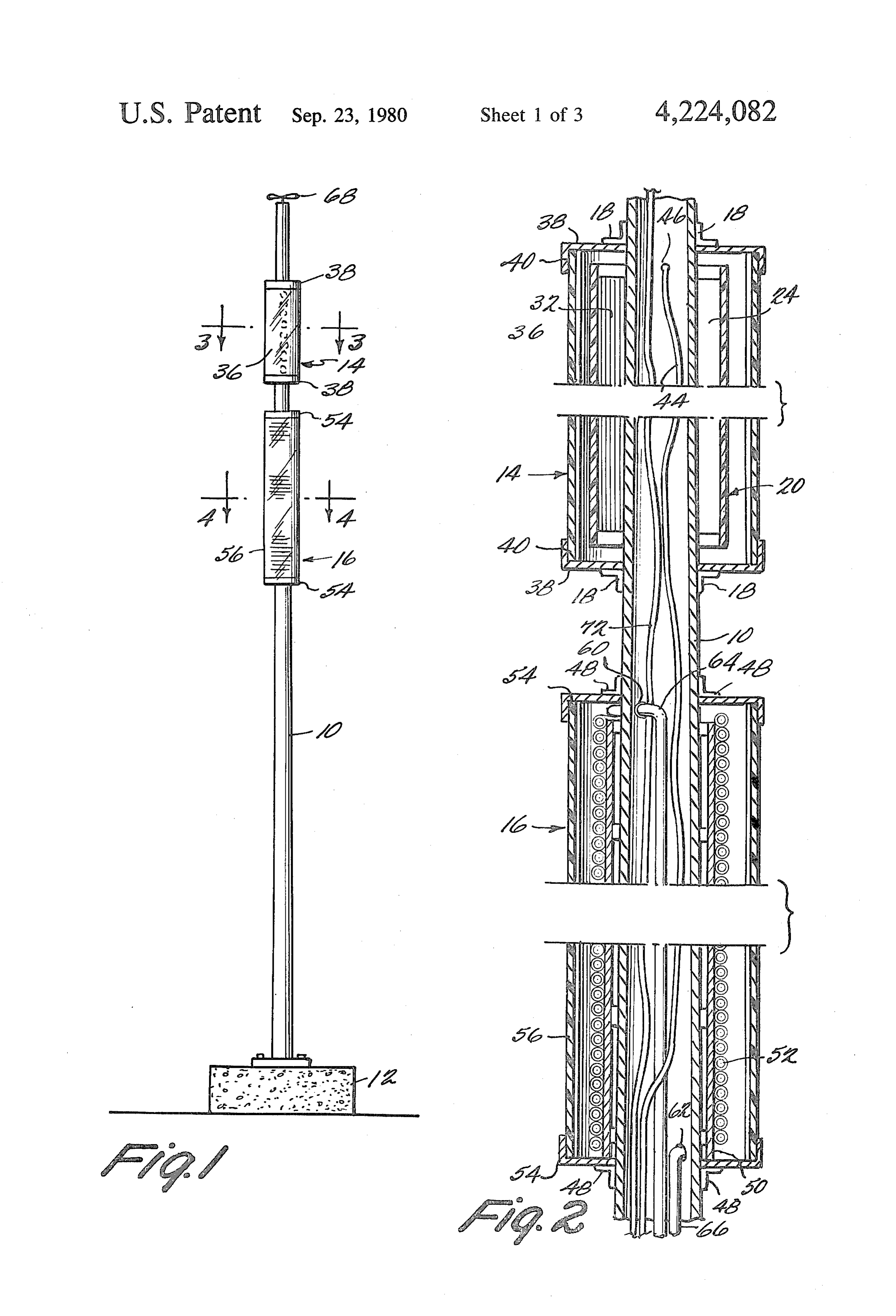
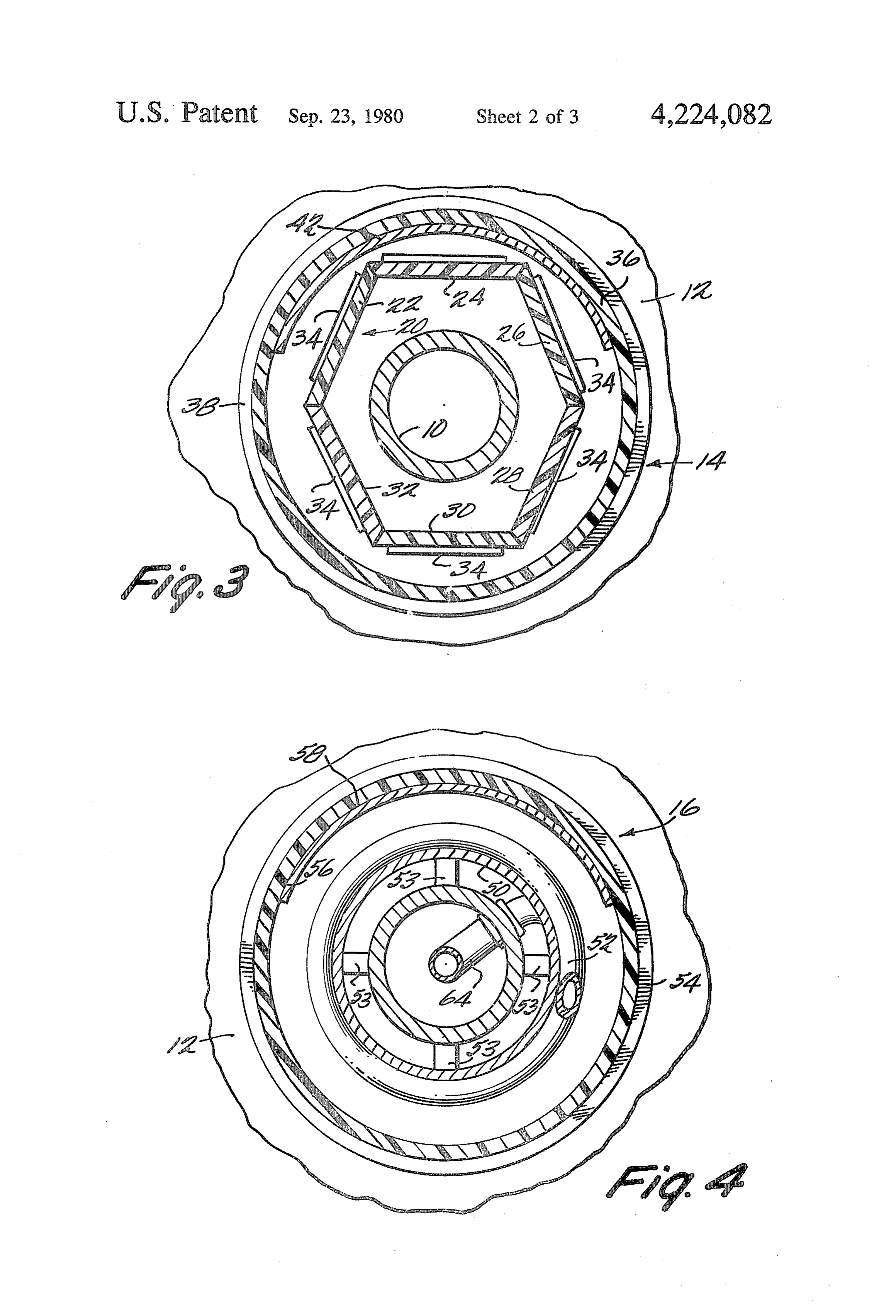
air screen for maintaining an ambient air chamber. To These and other objects and advantages of the inven intensify the amount of solar energy striking the helical tion will become more apparent and more readily ap 6 preciated from the following detailed description of the Heat transducer 16 is attached to pole 10 by means of presently preferred exemplary embodiment of the in brackets 48 (see FIG. 2). As illustrated in FIGS. 2 and vention taken in conjunction with the accompanying 4, tubing 52 is coiled upon support 50 within heat trans drawings, of which: ducer 16. Support 50 and tubing 52 run nearly the entire FIG. 1 is a side elevational of the present invention as length of heat transducer 16. Tubing 52 is painted black viewed looking north; to maximize heat absorption. It is preferred that tubing FIG. 2 is an enlarged fragmentary section of the solar 52 be wrapped tightly around support 50. As the wrap collectors of FIG. 1; ping process occurs, tubing 52 tends to flatten, thereby FIG. 3 is a cross-section taken along the III-III line increasing the surface area of the tubing exposed to the of FIG. 1; sun's rays. Obviously, this is desirable in that it increases FIG. 4 is a cross-section taken along the IV-V line the amount of energy that is transferred from the sun's of FIG. 1; rays to fluid passing through the tubing. In the pre FIG. 5 is a schematic of the plumbing of the present ferred embodiment, the fluid is water. invention; and Support 50 is held in place radially by spacers 53, and FIG. 6 is a schematic of the electrical circuit of the longitudinally by pans 54 which are connected to pole present invention. 10 by brackets 48. Pans 54 also support ambient air Referring now to FIG. 1, pole 10 is mounted on base shield 56 which creates an ambient air space around 12. In the preferred embodiment, pole 10 is made of tubing 52. In the preferred embodiment, ambient air aluminum and is tapered, having an outer diameter of shield 56 is cylindrical in shape and made of a clear six inches at the top and ten inches at the bottom. The 20 plastic such as lucite. Shield 56 helps insulate tubing 52 height of pole 10 is approximately thirty-four feet. from the cooler outside environment.
Those skilled in the art will realize that this corresponds In order to concentrate more solar energy on the fairly closely to poles used to suspend street lamps, and coils, reflector 58 is positioned on the inner face of the indeed such poles are ideally suited for this application. north side of ambient air shield 56. Reflector 58 reflects Attached to pole 10 is electrical energy transducer 14 25 solar energy which would otherwise pass through and heat transducer 16. In the preferred embodiment, transducer 16 and directs this energy to the portions of each of these transducers has an outer diameter of ap tubing 52 on the north side of support 50 which do not proximately sixteen inches. primarily receive direct solar energy. In the preferred Referring now to FIGS. 2 and 3, electrical transducer embodiment, reflector 58 is also made of a highly reflec 14 is attached to pole 10 by means of brackets 18. 30 tive mica sheet glued to ambient air shield 56. Within electrical transducer 14 is a hexagonal structure Tubing 52 passes through pole 10 at holes 60 and 62. 20 which extends the length of transducer 14. In the Rubber grommets in holes 60 and 62 insulate tubing 52 preferred embodiment, hexagonal structure 20 is com from pole 10 so that pole 10 does not act as a sink for posed of six interconnected lucite plates having refer energy passing through tubing 52. Portion 64 of tubing ence numerals 22, 24, 26, 28, 30 and 32. A plurality of 35 52 carries fluid up the center of pole 10, through hole 60 solar cells 34 are mounted on each of these plates (ten to the coils, while fluid from the coils passes through on each plate, in the preferred embodiment). In the hole 62, and portion 66 of tubing 52 carries the fluid preferred embodiment, each cell 34 is made of silicon down the center of pole 10. Thus, again, pole 10 not and is capable of generating 0.5 volts at 1.2 amps. only supports heat transducer 16, but also its hollow Enclosing solar cells 34 is transparent shield 36 which 40 core provides a convenient passageway communicating protects solar cells 34 from the environment and eases with the transducer which protects the tubing passing cleaning. In the preferred embodiment, shield 36 is clear therethrough.
plastic and cylindrical. Capping the ends of electrical It is also advantageous to include a wind energy to transducer 14 are pans 38. Brackets 18 are attached to electrical energy transducer at the top of pole 10. Such pans 38 which in turn support both shield 36 and hexag 45 a transducer may, for example, be comprised of propel onal structure 20. Vertical lips 40 (see FIG. 2) on pans ler 68 (see FIG. 1) and alternator 70 (see FIG. 6) posi 38 overlap shield 36 to mechanically position shield 36 tioned near propeller 68. Wires 72 from alternator 68 and ease the formation of a weather-tight seal between also run down the center of pole 10.
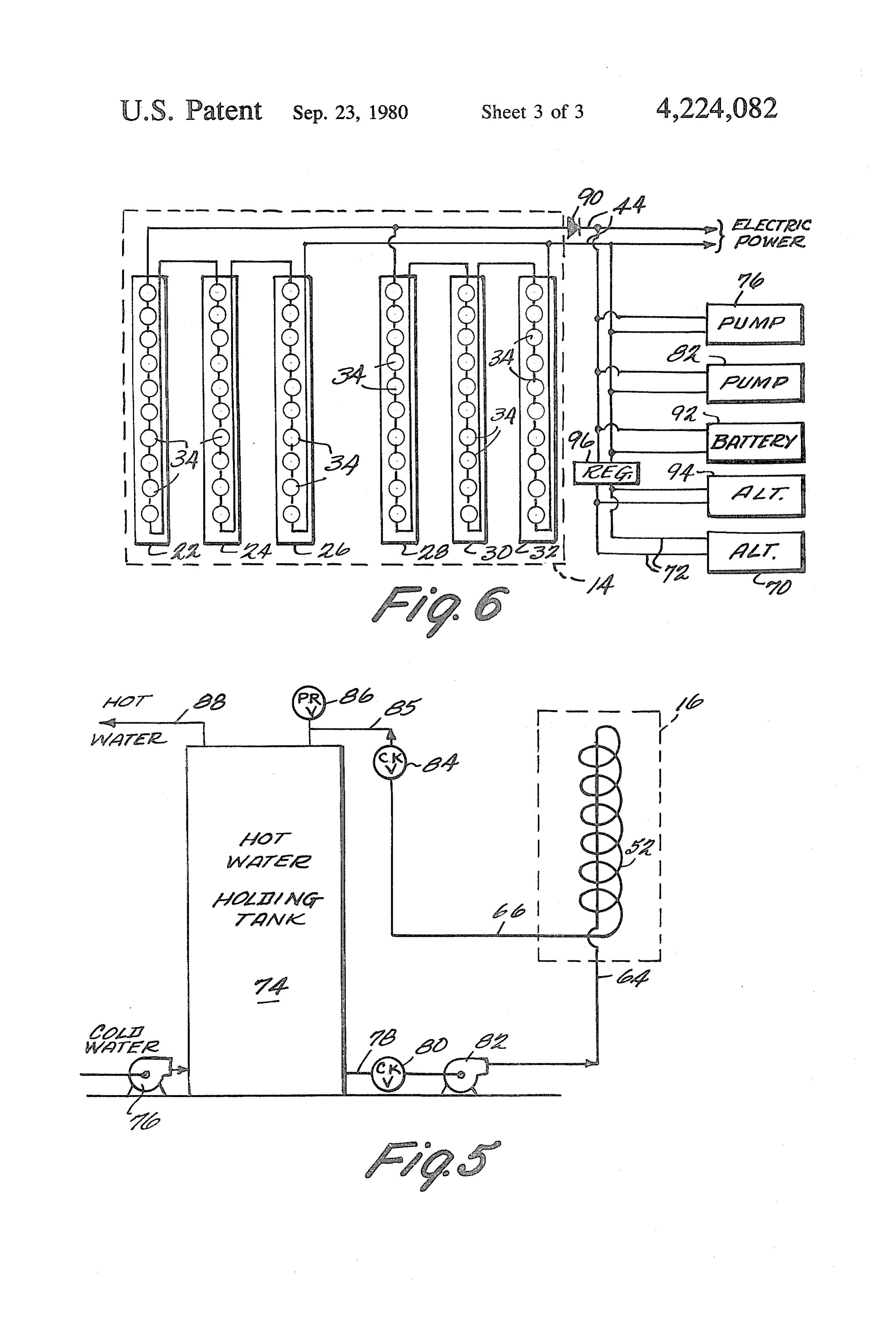
shield 36 and pans 38. FIG. 5 is a schematic of the plumbing connected to In this country, the sun always remains south of the 50 heat transducer 16. Tank 74 holds water heated by vertical. Therefore, southerly facing solar cells 34 on transducer 16. Cold water is supplied to tank 74 via plates 28, 30 and 32 receive more direct sunlight than pump 76 which maintains pressure in the system. In the northerly facing solar cells 34 on plates 22, 24 and 26. In heating process, water leaves the bottom of tank 74 via order to increase the amount of solar energy incident on line 78, and passes through check valve 80 which pro the solar cells, reflector 42 is attached to the northern 55 hibits the reverse flow of water therethrough. Water inner surface of shield 36. Reflector 42 reflects energy then passes through pump 82 which creates circulation to northerly facing solar cells 34 on plates 22, 24 and 26 through heat transducer 16. After the water has been to thereby increase the amount of energy converted heated in heat transducer 16, it passes through chcek into electrical energy. In the preferred embodiment, valve 84 which also prevents the reverse flow of water, reflector 42 is made of a highly reflective mica glued to 60 before reentering tank 74 at the top via line 85. Pressure the inner surface of shield 36. release valve 86 prevents an excessive buildup of pres Wires 44 (see FIG. 2) attached to solar cells 34 pass sure due to thermal expansion. Hot water is drawn off through hole 46 and extend down the central core of the top of tank 74 via line 88 for any desired use. An pole 10. Thus, pole 10 not only supports electrical en independently powered water heated may also be ergy transducer 14, but also its hollow core provides a 65 added to supplement heat transducer 16. convenient serviceway communicating with electrical FIG. 6 illustrates the electrical connections to solar transducer 14 which protects wires 44 passing there cells 34. The solar cells 34 attached to each of sections through. 22, 24, 26, 28, 30 and 32 of hexagonal structure 20 are 7 connected in series. The three sections 22, 24 and 26 of a pole adapted to be vertically disposed; hexagonal structure 20 facing north are connected in a solar energy to heat transducer mounted on said series, and the three sections 28, 30 and 32 of hexagonal pole, said heat transducer including tubing heli structure 20 facing south are connected in series. The cally disposed about said pole, a transparent shield cells 34 of the three sections 22, 24 and 26 facing north, disposed about and enclosing said tubing, and re are then connected in parallel with the cells 34 of the flecting means for reflecting sunlight to the portion three sections 28, 30 and 32 facing south. Since each cell of said tubing not directly illuminated by the direct 34 is capable of producing 0.5 volts at 1.2 amps, each of rays of the sun;
sections 22, 24, 26, 28, 30 and 32 of hexagonal structure a solar energy to electrical energy transducer 20 generates five volts at 1.2 amps so that each of the 10 mounted on said pole;
combination of the three northward facing sections 22, means for conducting heat generated by said heat 24 and 26 and the combination of the three southward transducer from said heat transducer; and facing sections 28, 30 and 32 generates 15 volts at 1.2 means for conducting the electrical energy generated amps. Therefore, the total output of solar cells 34 as by said electrical energy transducer from said elec connected is 15 volts at 2.4 amps. Diode 90 prevents a 15 trical energy transducer. reverse flow of current into cells 34. The generated 4. A solar energy collector as in claim 2 or 3 wherein power may be used to drive pumps 76 and 82, in addi said electrical energy transducer comprises: tion to supplying electrical power for any desired use, a plurality of solar cells disposed about said pole, said such as lighting of a house. Excess electrical power may solar cells being organized in first and second be stored in storage battery 92. If the energy produced 20 banks, the solar cells of said first bank primarily by cells 34 is not sufficient to supply all of the electrical being adapted for receiving the direct rays of the needs for the particular end use, battery 92 supplies sun, the solar cells of said second bank primarily additional power. If battery.92 discharges, alternator 94 not being adapted for receiving the direct rays of may be connected to the system through voltage regula the sun; and tor 96. Alternator 70 of the wind transducer may also be 25 means for reflecting sunlight to said second bank. connected to battery 92 and the system generally 5. A solar energy collector as in claim 4 wherein said through regulator 96. In the preferred embodiment, first bank and second bank are electrically connected in alternator 70 will trickle charge battery 92 even at parallel.
night. 6. A solar energy collector as in claim 1, 2 or 3 Only one exemplary embodiment of this invention 30 wherein: .. . .
has been described in detail above. Those skilled in the said heat conducting means comprises a first conduit art will readily appreciate that many modifications are for conducting a fluid to said heat transducer and a possible in the exemplary embodiment without materi second conduit for conducting said fluid from said ally departing from the novel teachings and advantages heat transducer; and of this invention. For example, additional energy trans 35 said apparatus further comprises: ducers, solar, heat, wind or otherwise, may be attached : heat storing means adapted to be at least partially to pole 10. In addition, the pole may be hinged at the filled with said fluid;
bottom so that it may be easily lowered for maintenance means for controlling the entry of unheated fluid into and cleaning. Furthermore, cold water may enter the said heat storing means;
plumbing system in line 78. Hot water may be drawn a third conduit connecting said heat storing means to out of the system from line 85. said first conduit for conducting fluid from said Accordingly, all such modifications are intended to heat storing means to said first conduit; be included within the scope of this invention as defined a fourth conduit connecting said heat storing means in the following claims. to said second conduit for conducting fluid from What is claimed is: 45 said second conduit to said heat storing means; 1. A solar energy collector comprising: a first check valve disposed in said third conduit; a pole adapted to be vertically disposed; a second check valve disposed in said fourth conduit; a solar energy to heat transducer mounted on said pumping means for circulating fluid from said heat pole; storing means through said third conduit, first con a solar energy to electrical energy transducer 50 duit, said heat transducer, said second conduit and mounted on said pole; said fourth conduit to said heat storing means; and means for conducting heat generated by said heat means for conducting heated fluid from said heat transducer from said heat transducer; and storing means.
means for conducting the electrical energy generated 7. A solar energy collector as in claim 1, further com by said electrical energy transducer from said elec 55 prising a wind energy to electrical energy transducer trical energy transducer. mounted on said pole.
2. A solar energy collector comprising: 8. A solar energy collector comprising: a pole adapted to be vertically disposed; a pole adapted to be vertically disposed; a solar energy to heat transducer mounted on said a solar energy to heat transducer mounted on said pole; 60 pole;
a solar energy to electrical energy transducer a solar energy to electrical energy transducer mounted on said pole above said heat transducer; mounted on said pole comprising a plurality of means for conducting heat generated by said heat solar cells disposed about said pole, said means for transducer from said heat transducer; and reflecting sunlight to those of said solar cells not means for conducting the electrical energy generated 65 primarily adapted to be directly illuminated by the by said electrical energy transducer from said elec rays of the sun;
trical energy transducer. means for conducting heat generated by said heat 3. A solar energy collector comprising: transducer from said heat transducer; and 8 means for conducting the electrical energy generated means for conducting the electrical energy generated by said electrical energy transducer from said elec by said electrical energy transducer from said elec trical energy transducer. trical energy transducer.
9. A solar energy collector as in claim 3 or 8 wherein 13. A solar energy collector comprising: said electrical energy transducer is disposed on said a pole adapted to be vertically disposed; pole above said heat transducer. a solar energy to heat transducer mounted on said 10. A solar energy collector as in claims 2 or 8 pole including:
wherein said solar energy to heat transducer comprises: tubing helically disposed about said pole, f'bing helically disposed about said pole; a transparent shield disposed about and enclosing a transparent shield disposed about and enclosing said O said tubing, and tubing; and means for reflecting sunlight to the portion of said means for reflecting sunlight to the portion of said tubing not directly illuminated by the rays of the tubing not directly illuminated by the rays of the Sun;
S. a solar energy to electrical energy transducer 11. A solar energy collector comprising: mounted on said pole including: a pole adapted to be vertically disposed; a plurality of solar cells disposed about said pole, a solar energy to heat transducer mounted on said above said tubing, and pole, said heat transducer comprising tubing heli means for reflecting sunlight to the portion of said cally disposed about said pole, a transparent shield O plurality of solar cells not directly illuminated by disposed about and enclosing said tubing, and the rays of the sun;
means for reflecting sunlight to the portion of said means for storing heat adapted to be at least partially tubing not directly illuminated by the rays of the filled with a fluid;
first conducting means for conducting fluid from said a solar energy to electrical energy transducer heat storing means to one end of said tubing; second conducting means for conducting fluid from mounted on said pole above said heat transducer; the second end of said tubing to said heat storing means for conducting heat. generated by said heat (neans;
transducer from said heat transducer; and means for controlling the entry of unheated fluid to at means for conducting the electrical energy generated least one of said heat storing means and said first by said electrical energy transducer from said heat 30 conducting means;
transducer. pumping means for circulating fluid from said heat 12. A solar energy collector comprising: storing means, through said first conducting means, a pole adapted to be vertically disposed; said tubing, said second conducting means, to said a solar energy to heat transducer mounted on said heat storing means;
pole; 35 means for conducting heated fluid from at least one of a solar energy to electrical energy transducer said heat storing means and second conducting mounted on said pole above said heat transducer, means;
said electrical energy transducer including a plural a battery;
ity of solar cells disposed about said pole and means means for electrically connecting said plurality of for reflecting the rays of the sun to the portion of 40 solar cells to said battery; and said plurality of solar cells not directly illuminated means for conducting electrical energy from at least by the rays of the sun; one of said battery, said electrical connecting means for conducting heat generated by said heat means, and said: solar cells.
transducer from said heat transducer; and
Provenance
- Collection
- Patents citing this work
- Pages
- 8
- Method
- pdftotext (the PDF's own text layer) + pdftoppm 300dpi page scans
- Patent office record
- patents.google.com →
- Source
- Google Patents citing-documents table
- Assignee
- Independent Power Company, Inc.
- Published
- 1980-09-23
- Transcribed from
- patentimages.storage.googleapis.com →