

patent · US4296738A
Cylindrical solar energy collector
27 October 1981
Text
Page 1bibliographic recordscan →
United States Patent (19)
Kelton
54 CYLINDRICAL SOLAR ENERGY
COLLECTOR
76 Inventor: Wallace G. Kelton, 1748 NE. 58th St.,
Fort Lauderdale, Fla., 33334
Int. Cl. ...... ... F24J 3/02; F28F 1/00 52 U.S. Cl. .................................... 126/443; 165/163;
2,213,894 9/1940 Barry ................................... 126/443 3,853,114 12/1974 Gaydos ... 126/443 4,018,215 4/1977 Pei ............ ... 165/142 4,027,653 6/1977 Meckler ... ... 126/443 4,043,318 8/1977 Pei ....................................... 126/443 4,080,954 3/1978 de Wilde et al. .... ... 126/443 4,086,911 5/1978 Futch ....... ... 126/443 4,089,325 5/i978 Brola ..................... .............. 26/443
4,120,285 10/1978 Nugent ................................ 126/443 4,186,724 2/1980 Nelson ................................ 126/443 4,215,674 8/1980 Riggs et al. ......................... 126/443 Primary Examiner-Daniel J. O'Connor
Attorney, Agent, or Firm-John J. Byrne
A solar energy collector 16 for utilizing the energy of the sun to heat a working fluid. The collector comprises a core conduit 30 having a working fluid inlet end 32 and a closure 38 fitted across the other end. A single return conduit 42 is spirally wound upon the exterior surface of the core conduit, wherein the windings are in close lateral juxtaposition but with the return conduit and the core conduit both exposed to direct impinge ment of solar rays. A transparent tube 48 coaxially sur rounds the core conduit 30. Annular members 52 and 54 are positioned at each end of the transparent tube 48 to maintain the spatial relationship of the members and form an annular air insulation zone around the core conduit 30 and return conduit 42.
15 Claims, 4 Drawing Figures
Drawings
Page 2drawing sheetscan →
Page 3scan →
capable of heating a working fluid to a useful degree
CYLINDRICAL SOLAR ENERGY COLLECTOR with a single cycle of fluid transit through the unit. It is another object of the invention to provide a
BACKGROUND OF THE INVENTION novel solar energy collector wherein direct solar en This invention relates to a solar energy collector. 5 ergy rays may be utilized to heat an incoming working More specifically, this invention relates to a compact ture ofconduit fluid as well as further elevating the tempera working fluid in an outgoing fluid conduit, solar collector with improved structural stability and It is still another object of the invention to provide a efficiency of operation,
Solar collectors have been theorized for decades and O novel solar energy collector which may be operated basically operate on a principle of concentrating solar over a wide degree of conditions and circumstances energy to heat a working fluid or solution which can be with a high degree of safety. It is a further object of the invention to provide a transported, stored and utilized over an extended period novel solar energy collector which has an enhanced of time. Notwithstanding widespread knowledge of the degree of structural integrity over a wide range of envi above basic principle, solar energy collectors known in 15 ronmental the past have not achieved a high degree of commercial life cycle. loads and which will exhibit an advantageous acceptance and utilization. It yet a further object of the invention to provide a At least one previously known solar collector com novel solar energy collector which may be facilely prises a transparent tube which encloses a generally fabricated linear coaxial conduit which extends through the trans 20 condition, and maintained in an advantageous operating parent tube and then returns in a loose spiral pattern It is still a further object of the invention to provide a spaced about the linear conduit. A reflector member is novel solar energy collector wherein incoming working mounted within the transparent tube and is adjustable to fluid may direct solar rays onto the linear inlet and spiral return in a returnbeconduit.heated and mixed prior to further heating conduits. While this system offers a degree of theoreti 25 cal appeal, fluid flow within the collector is constant BRIEF SUMMARY OF THE INVENTION because the size of the tube is constant. Accordingly, flow rates must be very low or a number of units must ferredsolar
A energy collector, in accordance with a pre be tied in series to provide effective heating. In addition, to achieve at least of embodiment the invention, which is intended some of the foregoing objects in mechanisms which are employed to continuously regu 30 cludes a generally linear core conduit having a working late reflector position are subject to mechanical failure fluid inlet and a closure fitted across the other end of the over the course of time.
Another previously known system comprises a first into the other end of the core conduitisinlaterally core conduit. A single return conduit tapped a posture adja linear inlet conduit and a second coaxial conduit which is corrugated to define a double series of helically ex 35 cent to but axially spaced from the core conduit closure and is spirally wound about the exposed core conduit.
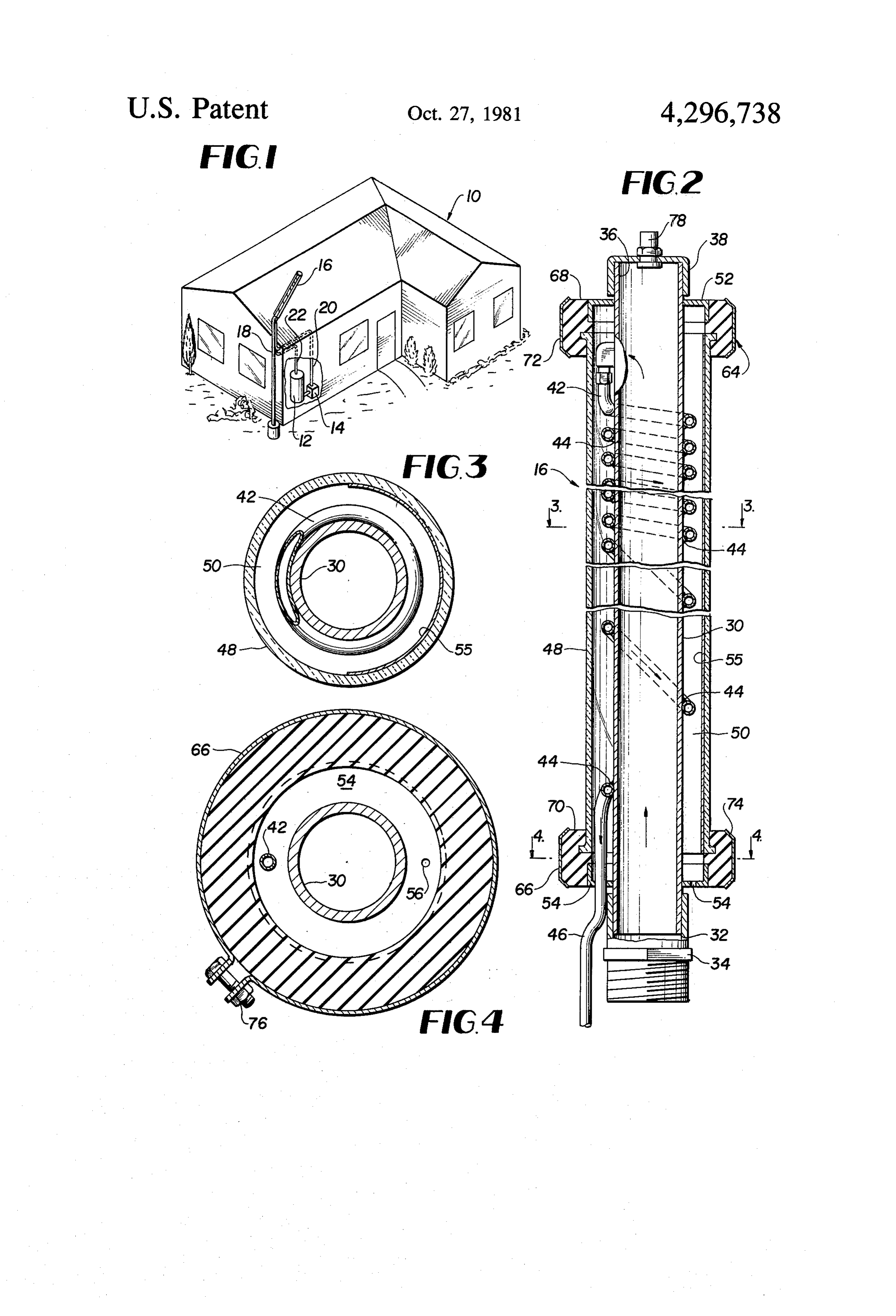
tending ridges and valleys. The corrugations serve to The form a return spiral flow path along the entire length of may windings of the return conduit in an upper portion be in close lateral juxtaposition and serve to slowly the inlet conduit. A transparent heat shield coaxially return a working fluid while being heated by direct surrounds both the first and second conduits and a para application of solar energy to the return conduit. In a bolic reflecting surface is mounted at a distance about 40 lower section of the linear core conduit the degree of the heat shield to focus solar energy onto the exterior spacing between adjacent return conduit windings may surface of the second conduit. This system completely be greatly increased such that only one or two turns isolates the first conduit from direction application of exist around the lower portion of the linear core con solar energy from the sun. Additionally the dual return duit. In this zone increased solar energy rays fall di path provides a rapid return that does not permit maxi 45 rectly on the core conduit to rapidly heat incoming mum utilization of the heating potential of the unit. Still working fluid while heat loss from the returning heated further, the close proximity of the transparent heat fluid is minimized. A transparent tube coaxially sur shield to the second conduit does not permit full utiliza rounds the core conduit and is dimensioned to form an tion of a potential for insulation of the conduit elements. annular space around the core and return conduit. An Finally the parabolic reflector element is positioned by 50 nular members are positioned at each end of the trans cantilever supports at a distance that jeopardizes the parent tube to maintain the spatial relationship of the mechanical integrity of the unit in high winds, etc. conduit members and to form an annular air insulation The difficulties suggested in the proceeding are not zone about the core conduit and return conduit. intended to be exhaustive, but rather are among many THE DRAWINGS which may tend to reduce the effectiveness and user 55 satisfaction of prior solar energy collector devices. Other objects and advantages of the invention will Other noteworthy problems may also exist; however, become apparent from the following detailed descrip those presented above should be sufficient to demon tion of a preferred embodiment thereof taken in con strate that solar energy collectors appearing in the past junction with the accompanying drawings wherein: will admit to worthwhile improvement. 60 FIG. 1 is an axonometric view of an operative envi OBJECTS OF THE INVENTION ronment suitable to advantageously utilize a solar en ergy collector in accordance with the subject invention;
It is therefore a general object of the invention to FIG. 2 is a partially sectioned, and broken away, provide a novel solar energy collector which will obvi detail side view of a solar energy collector in accor ate or minimize difficulties of the type previously de dance with a preferred embodiment of the invention; scribed. FIG. 3 is a cross-sectional view taken along section It is a specific object of the invention to provide a line 3-3 in FIG. 2 and discloses a return conduit novel solar energy collector which is compact and , wrapped around a central core conduit both of which 4 are enclosed within a transparent cylinder having a heat application to the central core conduit and at the semi-cylindrical reflection member; and same time minimizes heat loss of fluid within the return FIG. 4 is a cross-sectional view taken along section conduit to the core conduit before it exits into a return line 4-4 in FIG. 2 and discloses an annular clamp mem conduit 24.
ber and an air bleed hole in an annular end member to The core conduit and return conduit are preferably equilize pressure on the interior of the transparent cylin fabricated from a metallic material with a high coeffici der with ambient pressure. ent of heat conduction such as copper, aluminum, or the DETAILED DESCRIPTION like. The conduits are chemically surfaced treated, plated or painted to enhance the heat absorption charac
Referring now to the drawings and particularly to 10 teristics and reduce the heat transmission capability of FIG. 1 thereofthere will be seen an axonometric repre the conduits. In this regard the conduits may be painted sentation of an operative environment suitable to advan with a black coating having a rough exterior surface so tageously utilize a solar energy collector in accordance that solar energy is advantageously trapped by the con with a preferred embodiment of the subject invention. duits.
More specifically, a building 10 such as a residence, 15 A transparent tube 48 coaxially extends about the office building, or the like is provided with a working core conduit 30 and is dimensioned to have a diameter fluid storage container 12 having an insulation cover sufficiently greater than the diameter of the core con which is conventional in the art. A pump 14 is utilized duit so as to create an annular air insulation zone 50 to draw working fluid from the collector 12 and to which enropes the core conduit 30 and return conduit pump it upwardly to solar energy collector 16 posi 20 42. Annular members 52 and 54 are positioned at oppo tioned adjacent the building. site ends of the core conduit 30 and transparent tube 48 The collector 16 is attached to a post or column 18 and serve to hold the members in rigid spatial relation which is supported upon a ground surface by a buried ship and enclose the air insulation zone 50. An air bleed concrete block or the like. Although a single collector is aperture 56 is fashioned through at least annular mem disclosed it is contemplated that a plurality of collectors 25 54, note may be mounted upon a single or dual support towers as ber ously
FIG.4, to enable air pressure to be continu equalized between the interior heat insulation desired. The collector(s) are connected to the storage container 12 by a separate supply conduit 20 and a re zone 50 and the ambient air pressure. A reflector element 55 is contiguously mounted turn conduit 22.
within the transparent cylinder 48 and may optimumly
Turning now to FIG. 2 there will be seen a detailed 30 comprise cross-sectional view of a solar energy collector 16 in 3. Alternatively a semicylindrical shell, note particularly FIG. accordance with a preferred embodiment of the inven member 48 may the be inner surface of the transparent provided with a highly reflective tion. More specifically, a generally linear core cylinder plating.
30 has an inlet end 32 which is mated with a threaded adapter 34 which in turn may be coupled to the working 35 byThe the structural integrity of the system is maintained provision of an upper 64 and a lower 66 mechani fluid inlet or supply 20. The inlet end 32 of the linear cal clamp assembly. More specifically, resilient ring core 30 is provided at the other end 36 with a cover members 68 and 70 respectively are provided with in closure or cap 38 to fluidically close the upper end of wardly contoured surfaces to cooperatively the inlet conduit and form a working fluid mixing cham peripheral elements of annular ring membersengage the
A 90' tapping joint 40 is mounted at the other end of as well as the end-most portions of the transparent tube the core conduit 30 in a posture which is adjacent to but 48. Metallic clamp rings 72 and 74 are fitted about the laterally spaced from the end closure 38 and provides a resilient members 68 and 70 respectively and are releas fluid outlet for heated working fluid from the core con ably held in position by mechanical fastening units such duit. A single return conduit 42 is connected to the joint 45 as nut and bolt combinations 76, note FIG. 4. The core 40 and in an initial stage of return flow, the conduit 42 conduit 30 is fitted at its upper end with an excess pres is spirally wound about the core conduit 30 in intimate sure release valve 78 which may be of a type known in heat transfer relationship wherein the lateral spacing the art.
between adjacent windings is approximately equal to In operation relatively cool working fluid enters the the diameter of the return conduit. In order to increase 50 solar collector 16 and is pumped upwardly through the the heat transfer coupling of the return conduit 42 with large diameter, linear core, conduit 30. In a preferred the generally linear core 30 the windings may be brazed embodiment this conduit has a diameter of 6 inches and or welded at the spiral junction locations 44 as the con length of 6 feet. As the fluid slowly rises in the conduit duit spirally wraps around the core 30. At approxi ittheis core heated by direct impingement of solar energy upon conduit. At the other end of the conduit 30 mately a mid-point location on the return conduit the 55 spacing between adjacent windings greatly increases warmed fluid within the conduit is reversed and mixed such that on a lower half of the core conduit, only one prior to entering into the spiral return conduit 42. Fluid or two windings of the return conduit are made before within the return conduit is further heated by direct the conduit reaches a posture generally adjacent the impingement of solar energy upon the exterior of the inlet end of the core as at 46. 60 return conduit. In one embodiment once the return In the upper zone of relatively close spacing, solar conduit reaches approximately a mid-point of the core energy will directly impinge upon the return conduit to conduit, the slope of the spiral is increased to enable an heat returning fluid slowly flowing therethrough and at increased amount of direct solar energy to be imparted the same time directly impinge upon an upper portion of to the inlet end of the core. In a preferred embodiment the core conduit between the windings to heat working 65 the return conduit is of an inch in diameter and 76 feet fluid within the core. In a lower portion of the core in length. This preferred dimensional relationship pro conduit, where cooler incoming fluid exists, the wide vides the core conduit with a flow area which is 64 spacing of the return conduit permits maximum direct times greater than the flow area of the return conduit.
Page 5scan →
In describing a solar energy collection in accordance 1. A solar energy collector for utilizing solar energy with a preferred embodiment of the invention, those to heat a working fluid, said solar energy collector skilled in the art will recognize several advantages comprising:
which singularly distinguish the invention from previ a generally hollow metallic core cylinder having a ously known devices. working fluid inlet at one end thereof and closure A particular advantage of the invention is the provi means fitted across the other end thereof; sion of a relatively large diameter linear inlet conduit a single metallic return conduit means having an inlet and a single return flow conduit which is compactly end tapped into said core cylinder in a posture gener wrapped about the core conduit. In one embodiment an ally at the other end of said core cylinder and a fluid upper portion of the core has a spacing approximately 10 outlet end extending generally adjacent to said inlet equal to the return conduit diameter and an increased end of said core cylinder, spacing in a lower position. This spaced combination of said return conduit means being wrapped in intimate wrappings provides for maximum heating of the work heat exchange contact about said core cylinder; ing fluid within an upper section of the conduit which is 15 transparent cylindrical tube means coaxially mounted then quickly delivered to a storage cylinder for future about said core cylinder and having a diameter suffi Se. ciently greater than said core cylinder such that a Additionally, the structural arrangement of the inner peripheral space exists between the interior of said and outer conduits permits direct solar energy to be transparent cylinder and the exterior of said return utilized to heat the inner conduit and the relatively cool 20 conduit means wrapped about said core cylinder; and working fluid at the inlet. At the upper end of the core annular means at each end of said transparent cylinder conduit, direct solar energy is further permitted to means and said core cylinder for maintaining the contact the inner conduit as well as the exterior or re spatial coaxial relationship of said core cylinder turn conduit. within said transparent cylindrical tube means and for The air bleed aperature as well as the safety release forming an annular air insulation chamber around valve provides for pressure equalization and safety reg 25 means,said core cylinder and said metallic return conduit ulation of the system over a wide range of environmen wherein working fluid may be pumped into tal and/or operating conditions. said core cylinder, pass through said core cylinder The unit is structurally rugged and compact with no and said metallic return conduit within said transpar moving parts or delicate mountings so as to ensure a 30 ent the tube means and be heated by solar energy within air insulation envelope.
long operating life for the unit.
Where maximum heating is desired, a plurality of to heat solar2. A energy collector for utilizing solar energy working fluid as defined in claim 1 and further units may be mounted upon a single pole or tower. The comprising:
novel structural arrangement of the large linear core and small exterior return conduit wrapped about the 35 generally semi-cylindrical reflector means mounted adjacent to but spaced from said core cylinder and core with direct solar heating of both provides a com said metallic return conduit means for reflecting pact system which will effectively heat a working fluid solar rays onto said core cylinder and said metallic to a useful degree without requiring a large amount of return conduit.
space and/or series coupling of the units. 3. A solar energy collector for utilizing solar energy In an optimum embodiment the cross-sectional area 40 heat a working fluid as defined in claim 1 or 2 and of the core conduit is 64 times as great as the cross-sec to further comprising:
tional area of the single return conduit. This dimen heat absorption coating means applied upon the ex sional relationship permits the collector unit to apply a posed surfaces of said metallic core cylinder and high concentration of solar energy to the working fluid said metallic conduit means. as it passes through the system and thus enables the unit 45 4. A solar energy collector for utilizing solar energy to operate as a single unit. to heat a working fluid as defined in claim 1 and further The mechanical coupling of the unit at an upper and comprising:
lower end thereof in cooperation with a contiguous automatic pressure relief valve means mounted upon interior reflector permits manual adjustment of the re said end closure means of said metallic core cylin flective unit to an optimum seasonal posture without 50 der.
adding complexity to the structure. 5. A solar energy collector for utilizing solar energy Additionally the compact character of the unit, to heat a working fluid as defined in claims 1 or 4 and which may functionally replace an entire roof mounted further comprising:
panel enables intallation without disturbing an existing at least one air-pressure equilizing aperature provided roofing surface or requiring extra bracing and the like of 55 through said annular means at at least one end of the roof. said transparent cylindrical means. Still further, the provision of the return conduit tap 6. A solar energy collector for utilizing solar energy downstream of the outer end of the core conduit pro to heat a working fluid as defined in claim 1 wherein: vides a working fluid mixing chamber or zone at the the cross-sectional area of said core cylinder is sub upper end of the conduit to minimize the occurrance of 60 stantially greater than the cross-sectional area of heat flow planes within the collector. said single return conduit means. In describing the invention, reference has made to a. 7. A solar energy collector for utilizing solar energy preferred embodiment. Those skilled in the art, how to heat a working fluid as defined in claim 6 wherein: ever, and familiar with the disclosure of the subject the cross-sectional area of said core cylinder is 64 invention, may recognize additions, deletions, modifica 65 times greater than the cross-sectional area of said tions, substitutions and/or other changes which will fall single return conduit means. within the purview of the subject invention and claims. 8. A solar energy collector for utilizing solar energy What is claimed is: to heat a working fluid as defined in claim 1 wherein:
Page 6scan →
said return conduit means being spirally wound about ent tube means and be heated by solar energy within said core cylinder and with the windings thereof the air insulation envelope.
being mutually juxtaposed but laterally spaced on 10. A solar energy collector for utilizing solar energy approximately half of the cylinder core beginning 5 to the heat a working fluid as defined in claim 9 wherein: lateral surfaces of said spiral windings of said at said other end thereof and approximately the return conduit means being mutually juxtaposed other half of said core cylinder being substantially but laterally spaced on approximately half of the without windings of said return conduit means and cylinder core beginning at said other end thereof exposed directly to solar rays. and approximately the other half of said core cylin 9. A solar energy collector for utilizing solar energy 10 der being substantially without windings of said to heat a working fluid, said solar energy collector return conduit means and exposed directly to solar comprising: rays.
a generally hollow core cylinder having a working fluid 11. A solar energy collector for utilizing solar energy inlet at one end thereof and closure means fitted to heat a working fluid as defined in claim 10 and fur across the other end thereof; 5 ther comprising:
a single return conduit means having an inlet end tapped at least one air-pressure equilizing aperture provided into said core cylinder in a posture generally at the through said annular means at at least one end of other end of said core cylinder and a fluid outlet end said transparent cylindrical means. extending generally adjacent to said inlet end of said 20 12. A solar energy collector for utilizing solar energy core cylinder, to heat a working fluid as defined in claim 11 and fur said return conduit means being wound in intimate ther comprising:
automatic pressure relief valve means mounted upon spiral heat exchange contact about said core cylin said end closure means of said core cylinder. der, and 13. A solar energy collector for utilizing solar energy the cross-sectional area of said core cylinder being 25 to heat a working fluid as defined in claim 11 wherein: substantially greater than the cross-sectional area the cross-sectional area of said core cylinder is 64 of said return conduit means; times greater than the cross-sectional area of said heat absorption coating means applied upon the ex return conduit means. posed surfaces of said core cylinder and said return 14. A solar energy collector for utilizing solar energy conduit means; 30 to heat a working fluid as defined in claim 11 and fur transparent cylindrical tube means coaxially mounted ther comprising:
about said core cylinder and having a diameter suffi generally semi-cylindrical reflector means mounted ciently greater than said core cylinder such that a adjacent to but spaced from said core cylinder and peripheral space exists between the interior of said 35 said return conduit means for reflecting solar rays transparent cylinder and the exterior of said return onto said core cylinder and said return conduit. conduit means wrapped about said core cylinder; and to heatA solar 15. energy collector for utilizing solar energy a working fluid as defined in claim 1 or 9 annular means at each end of said transparent cylinder wherein:
means and said core cylinder for maintaining the spatial coaxial relationship of said core cylinder 40 saidlateral single return conduit is normally tapped into a surface of said core cylinder in a posture within said transparent cylindrical tube means and for adjacent to but axially spaced from said core cylin forming an annular air insulation chamber around der closure means wherein heated working fluid said core cylinder and said metallic return conduit within said core cylinder will abut against said means, wherein working fluid may be pumped into closure means and be reversed and mixed before said core cylinder, pass through said core cylinder 45 entering said single return conduit means.
and said metallic return conduit within said transpar
Provenance
- Collection
- Patents citing this work
- Pages
- 6
- Method
- pdftotext (the PDF's own text layer) + pdftoppm 300dpi page scans
- Patent office record
- patents.google.com →
- Source
- Google Patents citing-documents table
- Assignee
- Kelton Wallace G
- Published
- 1981-10-27
- Transcribed from
- patentimages.storage.googleapis.com →