

patent · US4355628A
Illuminated solar energy collector
26 October 1982
Text
Page 1scan →
United States Patent (19)
Watts
(54) illuminated solar energy
Collector
75) Inventor: Ralph M. Watts, Little Rock, Ark.
73) Assignee: John W. Lowery, Jacksonville, Ark.
52 U.S. Cl. .................................... 126/427; 126/438:
761,596 5/1904 Moss ................................... 126/438 2,213,894 9/1940 Barry .................................. 126A443 2,291,534 7/1942. Deppe ................................. 126A451 3,182,654 5/1965 Culling ........ ... 126451
3,934,573 1/1976 Dandini ............................... 126A443
4,043,315 8/1977 Cooper ............................... 264.38
4,048,982 9/1977 Pei ....................................... 126/450 4,056,093 11/1977 Barger ................................. 126'440 4,057,048 11/1977 Maine .................................. 126/440 4, 11, 184 9/1978 Fletcher .............................. 126/45 4, l 16,223 9/1978 Vasilantone ........................ 26/440 4, 136,670 9/1979 Davis .................................. 126/450 Primary Examiner-Daniel J. O'Connor
Attorney, Agent, or Firm-Stephen D. Carver
Solar collector apparatus equipped with self-contained illumination means. The apparatus comprises a gener ally spherical collector forced from upper and lower hemispherically shaped halves coupled together. A generally spirally wound heat exchange disposed interi orly of the collector at the center thereof warms a fluid with solar energy. A mirror disposed below the heat exchanger reflects solar energy toward it to improve efficiency. Incandescent lights disposed below the mir ror within the spherical collector may be actuated to provide an aesthetically pleasing and useful lighting effect.
5 Claims, 4 Drawing Figures
Drawings
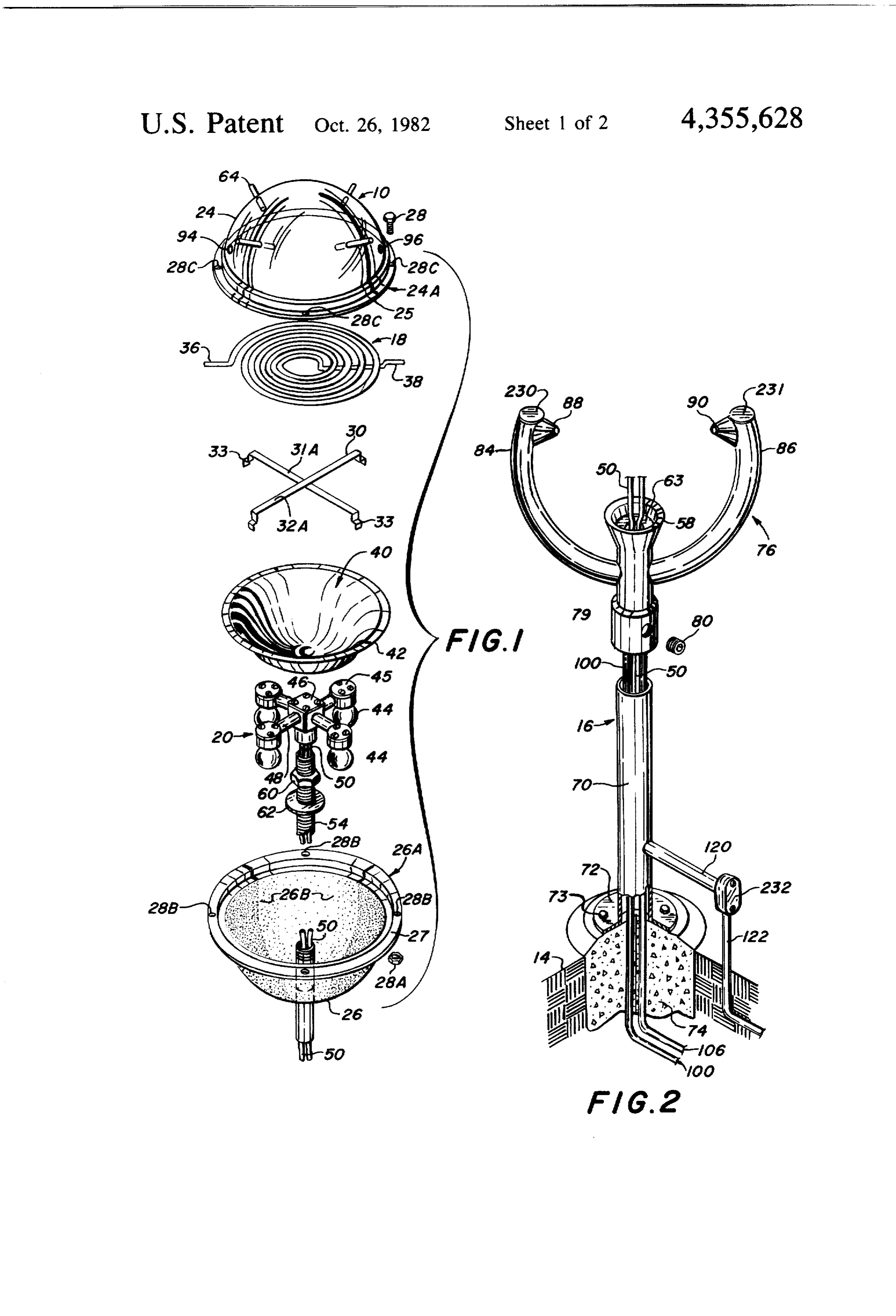
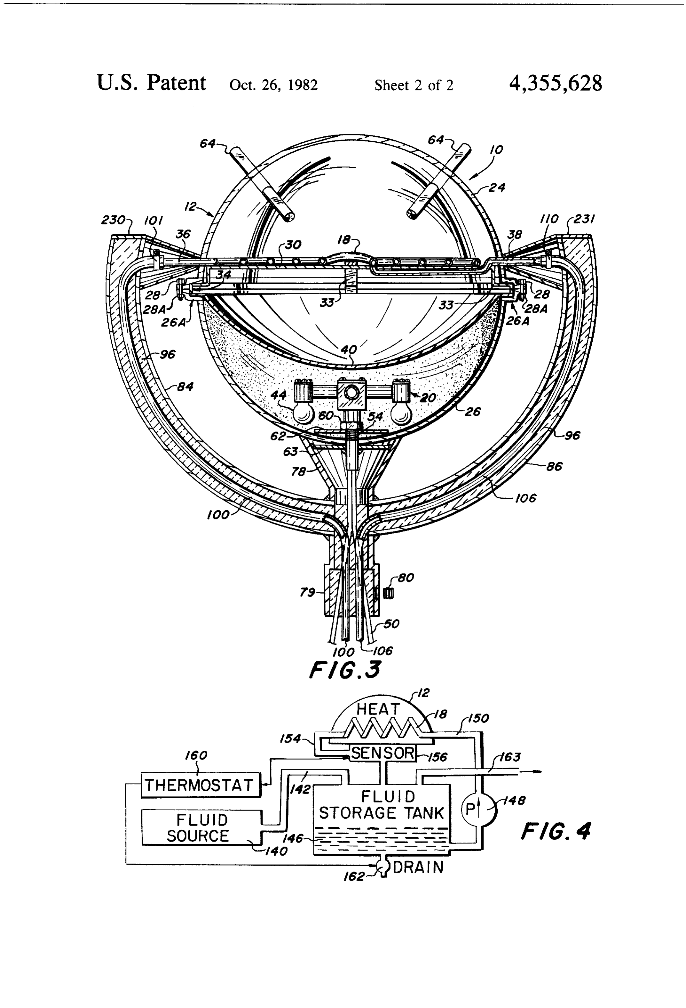
FIG. 2 is an isometric view of the support pedestal cal solar collector adapted to be exposed to sunlight for warming a fluid passing therethrough. The device may preferably thereof employed to mount the invention with parts broken away or shown in section for clarity;
Page 2drawing sheetscan →
Page 3drawing sheetscan →
Page 4scan →
It is a feature of this invention that the apparatus may be
ILLUMINATED SOLAR ENERGY COLLECTOR illuminated at night to provide a useful lighting func tion.
CROSS REFERENCE TO RELATED Another object of this invention is to provide a solar APPLICATION collector device of the character described which will This is a substitute application for Ser. No. 85,036, be inherently aligned with the sun, thus avoiding track filed Oct. 5, 1979, now abandoned. ing or aiming problems typically characteristic of prior art devices.
BACKGROUND OF THE INVENTION Another object of this invention is to provide a solar 10 energy collector unit which will be extremely resistant
This invention relates to solar energy devices. More particularly, this invention is concerned with a unit to winds and other natural elements. It is a feature of which employs solar energy to heat a fluid during the this invention that the generally spherical shape reduces day, which unit will function as an ornamentally attrac susceptibility to wind damage.
tive and functionally useful lighting system during the 5 Another object of this invention is to provide a solar night. energy collector unit which will be inherently pro In the prior art a plurality of solar collectors includ tected against otherwise deleterious accumulation of ing some form of enclosure comprised of generally ice, snow, moisture or the like. It is a feature of this translucent sides and housing some form of tube or coil invention that the self-contained illuminating feature for heat exchanging are well known. As will be appreci generates enough heat to prevent the build-up of ice, ated by those skilled in the art, most solar collectors are 20 snow or moisture.
generally "flat' or rectangular. Thus prior art devices These and other objects and advantages of this inven must be aimed at the sun for maximum efficiency. Usu tion, along with features of novelty appurtentant ally this means that a compromise position is reached thereto, will appear or become apparent in the course of for stationary installations facing generally south (in the 25 the following description.
northern hemisphere). Alternatively, it has been known in the past to provide some form of automatic tracking BRIEF DESCRIPTIONS OF THE DRAWINGS means whereby such flat collectors may be continu In the following drawings, which form a part of the ously aimed at the apparently moving sun. specification and which are to be construed in conjunc Besides the problems relating to solar tracking, prior tion therewith, and in which like reference numerals art solar collectors have been somewhat aesthetically 30 have been employed throughout to indicate like parts in unattractive. Moreover, most solar energy collectors the various views:
known to me are of very little usefulness at night. FIG. 1 is an exploded, isometric view of the invention SUMMARY OF THE INVENTION showing the construction of the generally spherical The present invention comprises a generally spheri 35 collector;
FIG. 2 is an isometric view of the support pedestal cal solar collector adapted to be exposed to sunlight for warming a fluid passing therethrough. The device may preferably thereof employed to mount the invention with parts broken away or shown in section for clarity;
thus be used for preheating water for a residential water FIG. 3 is an enlarged, assembled sectional view of the heater, for example. During periods of darkness illumi invention, nation means within the collector may be actuated to section forwith parts thereof broken away or shown in clarity; and, provide a useful lighting effect. FIG. 4 is a block diagram illustrating one manner in Preferably the apparatus comprises a spherical collec tor consisting of upper and lower hemispherical shaped which the present invention may be usefully employed. halves which are coupled together to house the internal DETALED DESCRIPTION OF THE parts of the apparatus. The spherical collector is rigidly 45 DRAWINGS mounted to a pedestal so that it will be secured above Turning now to the drawings, and more particularly ground. A generally spirally wound heat exchange tube enclosed within the apparatus received a working fluid to FIGS. 1 through 3 thereof, the reference numeral 10 generally designates an illuminated solar collector con to warm same from solar energy. A mirror located beneath the heat exchanger focuses energy toward it to 50 structed in accordance with the teachings of the present invention. The solar collector 10 comprises an upper, increase efficiency. Below the mirror within the spheri general spherical collector unit 12 which is adapted to cal collector unit a conventional electric lighting system be mounted above a supporting surface 14 (FIG. 2) via is employed. The lighting system may be actuated at night to provide an ornamentally pleasing outdoor a vertical pedestal 16 or similar mount. The apparatus is light, for example, and it is capable of use in a variety of 55 adapted to be mounted, for example, in the front or back other lighting applications. yard of a residence in an area exposed to sunlight. Dur Because of the generally spherical shape of the col ing the daytime a heat exchange coil 18 within the appa lector the unit will be constantly aimed at the sun. Thus ratus will warm a fluid circulating therethrough, thus tracking problems characteristic of certain prior art utilizing solar energy advantageously. Coil 18 may, for collectors are obviated. Moreover, the spherical shape 60 example, preheat water to be inputted into a hot water avoids aesthetic objections usually directed at conven heater, thereby saving energy. Also, during the night or tional flat solar collector units. an otherwise darkened condition lighting apparatus 20 Thus an object of this invention is to provide an en disposed within the spherical collector 12 may be actu ergy saving solar collection unit of aesthetically pleas ated to provide both ornamental lighting of the collec ing characteristics. 65 tor unit 10 and useful lighting of the surrounding area. Another object of this invention is to provide a solar The spherical collector 12 preferably comprises collector unit which, while being aesthetically pleasing, upper and lower generally hemispherically shaped will be of utilitarian merit both at night and in the day. halves 24, 26 which are adapted to be natingly coupled 5 together. It will be noted that each of the halves 24, 26 ingly coupled to the upper edge of shaft 70. Sleeve 79 is respectively defined about their bases. The invention permanently secured to shaft 70 with a set screw 80. A may be coupled together through nut and bolt assem pair of generally C-shaped mounting arms 84, 86 project blies 28, 28A adapted to be secured through flat flang outwardly from collar 58, terminating in generally lip portions 25, 27. cone-shaped projections 88,90, which are adapted to The inside surface 26B of the lower hemisphere 26 penetrate holes 94, 96 respectively provided within may preferably be frosted so as to more fully distribute upper hemisphere 24. In this manner the mounting arms light through the apparatus to produce a pleasing aes 76 will firmly and sealingly support the spherical collec thetic affect at night when illuminated. O.
The heat exchanger coil 18 is of generally spirally O It will be best observed in FIG. 3 that the mounting shaped configuration, and is adapted to be disposed arms 84, 86 are of generally tubular, arcuate construc within the collector 12 generally at the center thereof. tion. The arms are preferably filled with a polyurethane To this effect, a cross braced support means 30 is se insulative substance so as to prevent thermodynamic cured in place between the two hemispheres. It will be losses. A fluid conduction tube 100 provided in arm 84 noted that support means 30 comprises a pair of gener 5 is adapted to be coupled to the fluid input means 36 of ally elongated cross pieces 31A, 32A which terminate in the heat exchanger with a clamp 101. Similarly, fluid generally step-shaped feet 33. With reference now to output tube 106 is coupled to the fluid output 38 with a FIG. 3, it will be observed that the step-shaped feet clamp 110. It will be observed that the fluid input and portions 33 are matingly received and held in abutment output means 36, 38 comprising the ends of heat ex within the rectangular space 34 defined between the changer 18 are adapted to be physically outputted flanges 24A, 26A. The heat exchange means 18 includes through the upper hemisphere through the holes 94, 96 a pair of ends 36, 38 which may be utilized for the input and into mounting projections 88,90. Conduits 100, 106 and output of a working fluid. A preferably aluminum thus extend downwardly within arms 84, 86, into pedes or highly polished parabolic mirror structure 40 is dis tal sleeve 70, from which they extend to an application posed within the collector 12 below the heat exchanger 25 such as a water heater or the like. The electrical con 18. It will be observed that the flanged edge 42 of the ductors 50 providing power to the apparatus may be mirror is secured within space 34 in abutment with conducted through sleeve 54 into pedestal collar 58 and support brace legs 33. Thus mirror 34 and heat ex downward through sleeve 70. Then the conductors 50 changer 18 are ultimately held in place by fastening of may pass through a conduit 120, 122 for switching in the upper and lower hemispherical halves. The function side the residence or other facility at which the inven of mirror 40 is to concentrate and reflect energy toward tion is installed.
the heat exchange 18 thereby increasing the efficiency It will be observed that during operation heat or solar of the apparatus. energy passing through the preferably glass or acrylic A conventional preferably incandescent lighting sys spherical collector 12 will be reflected by mirror 40 tem 20 is disposed beneath the mirror 40 and secured 35 toward heat exchanger 18. A fluid, such as water, pass with the lower recesses of lower hemisphere 26. The ing through coil 18 will thus be warmed. At night, it incandescent lighting system includes a plurality of will be apparent that lighting of the bulbs 44 will pro radially spaced-apart incandescent light bulbs 44 duce desirable lighting effects. For example, the appara mounted in recepticles 45, which are coupled to a con tus itself will be illuminated, providing desireable aes ventional electrical junction 45 through conduit 48. 40 thetic characteristics and also providing illumination of Electrical conductors 50 of conventional construction nearby areas. It will be observed that heat generated by lead to remote switching apparatus (not shown) for the lighting apparatus will rise upwardly, vertically actuation of the incandescent bulbs 44 in the usual man through the apparatus where it will warm the spherical ner. The lighting fixture 46 is secured within the lower collector and thus prevent the build-up of snow or ice. hemisphere 26 to an elongated, threaded sleeve 54 45 Also, it will be apparent that the heat generated by the which extends through a recess provided in the lower incandescent bulbs will eliminate or drive off moisture hemisphere and is weldably secured to the flared pedes which might otherwise collect within the device. Since tal collar 58. Thus when nut 60 is tightened against the collector is spherical it will be apparent that wind washer 62 the apparatus will be secured above pedestal resistance will be reduced so that the apparatus will 16. 50 resist high winds. Furthermore, it will be apparent that As observed in FIGS. 1 and 3 a plurality of generally the collector remains properly aimed at the sun as long cylindrical, elongated stick lenses 64 are provided in as it is properly installed.
penetrating engagement with respect to upper hemi Turning now to FIG. 4, one possible application of sphere 24. The stick lenses are of conventional con the invention is illustrated. Conventional fluid source struction and are available from Bausch and Lomb. The 55 140 may deliver fluid through a conduit 142 to a storage function of lenses 64 is to concentrate or direct energy tank 146. A pump 148 in fluid flow communication with toward the heating coil 18 so as to raise or lower tem tank 146 may drive fluid through conduit 150 into the perature a desired amount. In this manner, for example, heating coil 18 disposed within the collector 12. the apparatus working fluid may be varied, and differ Warmed water or fluid may thus be outputted through ent temperature ranges may be accommodated. Of 60 a conduit 154 past sensor 156 back into the storage tank course magnifying lenses of alternative configurations 146. Sensor 156 may be employed to control thermostat may be employed. 160 to actuate drain 162 to output warmed fluid at a Pedestal 16 includes an elongated, vertical sleeve-like given temperature range. Also, hot water or hot fluid shaft 70 which is adapted to be coupled to a mounting may be drawn off in the usual manner from conduit 163. plate 72 secured through nuts 73 to a concrete founda 65 It is contemplated, for example, that in residential appli tion 74 provided within the ground 14. Upper arm cations the invention 10 may find primary application in structure 76 projects from collar 58, which includes preheating water going to conventional electric or fossil sleeve portion 79 thereof which is adapted to be mat fuel water heaters. Because of the obvious aesthetic 6 beauty of the device, it will be apparent that many of ing at least a portion thereof secured between said the conventional limitations of solar energy collectors flanged collector halves; will be overcome. Also, it will be apparent that the mirror means disposed within said collector for re device will perform very useful lighting effects at night, flecting solar energy toward said heat exchange means;
From the foregoing, it will be seen that this invention lighting means disposed interiorly of said collector is one well adapted to obtain all the ends and objects for selectively providing illumination, said lighting herein set forth, together with other advantages which means disposed between said mirror means and a are obvious and which are inherent to the structure. lowermost portion of said collector whereby heat It will be understood that certain features and sub 10 generated by said lighting means will warm the combinations are of utility and may be employed with collection unit thereby resisting build-up of the out reference to other features and subcombinations. moisture and accumulation of snow, ice and the This is contemplated by and is within the scope of the like; and, claims. pedestal means adapted to be disposed upon a sup As many possible embodiments may be made of the 15 porting surface for securely mounting said collec invention without departing from the scope thereof, it is tor at an elevated position above said surface. 2. The combination as defined in claim 1 wherein:
to be understood that all matter herein set forth or said pedestal is tubular; shown in the accompanying drawings is to be inter said collector is secured to said pedestal means via preted as illustrative and not in a limiting sense. 20 generally C-shaped, tubular mounting means; and What is claimed is: said heat exchange means fluid input means and fluid 1. An illuminated solar energy collection unit com output means extend through said mounting means prising: and said pedestal means for connection exteriorly a generally spherical collector adapted to be exposed of said collection unit.
3. The combination as defined in claim 2 including a to sunlight, said collector comprising upper and 25 plurality of adjustable lenses extending interiorly of said lower generally hemispherically shaped, flanged spherical collector for facilitating internal temperature halves adapted to be coupled together;
heat exchange means disposed within said spherical control.
4. The combination as defined in claim 3 including collector substantially at the center thereof for 30 generally C-shaped mounting arm means for supporting warming fluid passing therethrough with solar said spherical collector.
energy, said heat exchange means including fluid 5. The combination as defined in claim 4 wherein said input means and fluid output means; heat exchange means is of generally spirally shaped means for supporting said heat exchange means configuration. t within said collector, said supporting means includ 35
Provenance
- Collection
- Patents citing this work
- Pages
- 6
- Method
- pdftotext (the PDF's own text layer) + pdftoppm 300dpi page scans
- Patent office record
- patents.google.com →
- Source
- Google Patents citing-documents table
- Assignee
- John W. Lowery
- Published
- 1982-10-26
- Transcribed from
- patentimages.storage.googleapis.com →