

patent · US4391100A
Closed loop hermetically sealed solar power generator
5 July 1983
Text
Page 1bibliographic recordscan →
United States Patent (19)
Smith
(54) CLOSED LOOP HERMETICALLY SEALED
SOLAR POWER GENERATOR
Inventor: Derrick A. Smith, 1180 S. Seabreeze
Blvd., Fort Lauderdale, Fla. 33.316
Int. Cl. ........................... ..................... F03G 7/02 52 U.S. C. .............................. 60/641.11; 60/641.15;
1,101,000 6/1914 Willsie ................................... 60/641 1951,403 3/1934 Goddard .... ........... 60/641 2,636,129 4/1953 Agnew ............... ... 203/DIG. 1
3,414,481 12/1968 Kelly, Jr. ............................ 202/234 3,945,218 3/1976 Parker ..... ... 60/641 X 3,998,206 12/1976 Jahn ............ ... 60/641 X 4,010,378 3/1977 Tharpe et al. ... 60/693 X 4,166,769 9/1979 Dukess ........ . . 126/440 X 4,187,686 2/1980 Pommier. ... 60/641 X 4,192,145 3/1980 Tanaka .................................. 60/675 4,244,189 1/1981 Bliamptis .......................... 60/641.11 Primary Examiner-Allen M. Ostrager
Assistant Examiner-Stephen F. Husar
A closed loop sealed recirculatory water conservation solar power generator is provided herein. It includes a stationary hollow globular water boiler having a water inlet, a steam outlet conduit and a refractor lens win dow. A parabaterol reflector directs the sun's rays towards the refractor lens window to generate heat to boil the water. A primary steam-powered turbine is connected to the steam outlet conduit and is joined via a steam condensing radiator and a condenser to provide a water outlet which feeds a closed reservoir. A second ary water-powered turbine is provided for the genera tion of electricity and is connected to the reservoir in such a way that it is selectively driven by water from the reservoir. A valve automatically sequenced for periodic opening is provided, to permit flow of water from the reservoir to the secondary turbine to drive the turbine, and for periodic closing to cut off the flow of water to permit the secondary turbine to remain at rest. The effluent conduit feeds water back to the globular boiler. Finally, a check valve is provided in the effluent conduit to control the recirculating flow of water back to the globular boiler. Such solar power generator is thus very energy efficient and ecologically conservative since the water is returned to its original source when its work has been extracted.
1 Claim, 1 Drawing Figure
Drawings
Page 2drawing sheetscan →
Page 3scan →
from the condenser, a storage reservoir elevated above
CLOSED LOOPHERMETICALLY SEALED SOLA the first-mentioned reservoir, and a differential-pressure POWER GENERATOR conduit leading from the condenser to the storage reser voir. The problem apparently to be solved by this pat
BACKGROUND OF THE INVENTION 5 entee was to avoid the detrimental effect on the heat (i) Field of the Invention exchange characteristics of the presence of free air in This invention relates to a solar power generator theIncondenser circuit.
apparatus for harnessing energy from the sun and for 669,504 issued Aug.that a third system, provided by Canadian Pat. No.
1963 to Podolny, the patentee conserving the water so used by such apparatus. 10 desired to provide an arrangement for storing some of (ii) Related Application . This invention is related to applicant's copending the heat energy from the sun so that it might be utilized U.S. application Ser. No. 070,329 filed Aug. 27, 1979 during the intervals when the device was not exposed to (now U.S. Pat. No. 4,253,307). the radiant heat of the sun; and also to provide a power (iii) Description of the Prior Art plant in which a chemical compound was used which Electricity is one of the most widely used forms of 15 could be separated into its constituents electrically, energy. It is known that electricity may be produced by together with an arrangement for storing the constitu hydroelectric generators, combustion engines powered ents, to be later combined chemically for producing by expensive fuel, e.g. oil or natural gas, or by electro electrical energy for the powerplant. These ends were motive steam engines powered by coal, or by the use of 20 apparently met by a solar energy powerplant including nuclear energy. These procedures suffer the deficiency the combination of a boiler, a mirror for concentrating that they may use dimenishing non-renewable re radiant heat on the boiler, a turbine powered by vapor sources, and of pollution of the environment. under pressure from the boiler, and a generator driven It would be therefore be advantageous if electricity by the turbine in combination with an electrolysis de could be produced with the advantages pointed out 25 vice for separating a compound into its constituents, above but with fewer of the aforementioned disadvan storage means for the constituents, a fuel cell in which tages while conserving the water used in the production the constituents are combined to produce electrical thereof. energy, and control means for selectively connecting Many proposals have been made to achieve these the generator to the electrolysis device and to a load or ends. In one proposal, that provided by Canadian Pat. 30 connecting the fuel cell to the load. The problem thus No. 145,581 issued Jan. 28, 1913 to R. A. Fessenden, apparently solved by this patentee was to store the sun's apparatus was provided for obtaining power from the energy in the form of constituents of a chemical which sun's radiant energy, which included the combination of could later be recombined to provide electrical energy. a reservoir and a working fluid therein exposed to be heated by the sun's radiant energy, means for protecting SUMMARY OF THE INVENTION such fluid against loss of heat by convection, a low 35 (i) Aims of the Invention pressure turbine and means to operate it by that fluid, and an upper fluid reservoir and a lower fluid reservoir ingItgeneration is seen therefore that the primary object of provid of electrical energy both in the daytime combined to store energy generated by the turbine. The and at night while conserving the water used in the problem which that inventor apparently desired to generation thereof has solve was that of protection of the working fluid against by the present invention,notthisyetcanbeen solved. However, achieved by using heat loss by convection.
In another system, that provided by Canadian Pat. and pure, namely the sun, in conjunction with limitless a primary energy supply which is inexpensive, the par
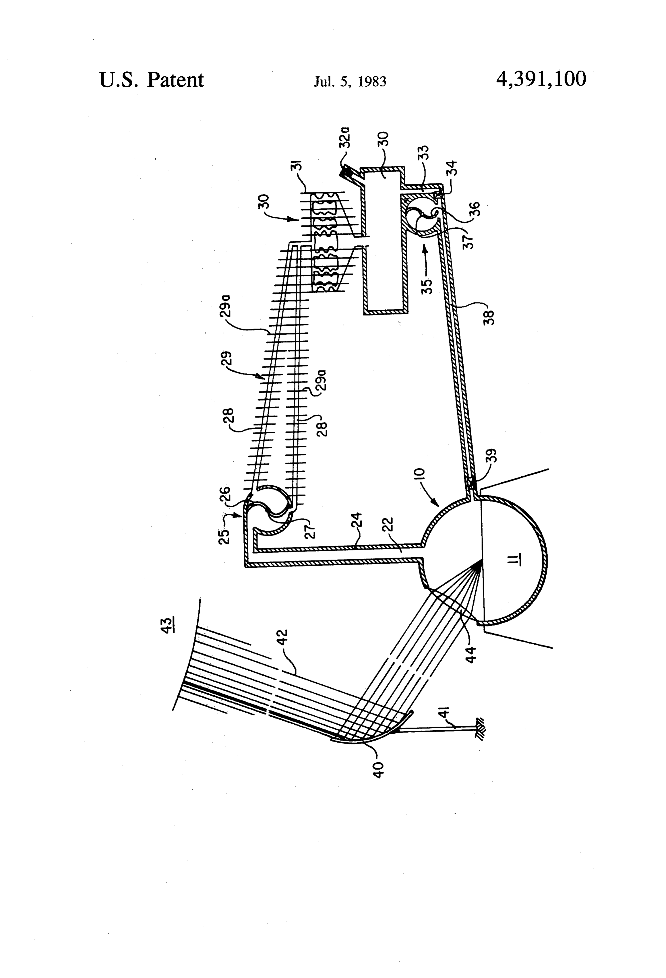
No. 505,536 issued Sept. 7, 1954 to Agnew, the patentee attempted to provide improved apparatus that utilized ticular construction to be described hereinafter. Thus, by this invention, a closed loop sealed recircu the energy of solar rays for effecting a temperature 45 latory differential between a quantity of water or other liquid providedwater conservation solar power generator is comprising: (a) a stationary hollow globular and the atmosphere thereabove, to conduct the resul boiler, the boiler including tant vapors to a higher level, and then to condense the adjacent the upper portionwater of the inlet means disposed globular boiler, an vapors and store the liquid thus provided. The vapors created power to generate electric current. A heat ex 50 upwardly directed steam outlet conduit originating change was effected between a source of water supply afrom the uppermost portion of the globular boiler, and refractor lens window disposed within an upper por and a quantity of the water obtained from the supply to tion of the globular boiler, the boiler being adapted to increase vaporization of the quantity of water. This was contain apparently solved by a solar engine including the con prising aa paraboloidbody of water; (b) controllable means com bination of a reservoir, a basin for receiving liquid from directing the sun's raysreflector towards mounted on a post for the refractor lens win the reservoir, a differential-pressure conduit extending dow to generate heat to boil water in the globular from the reservoir to the basin for passing liquid into the boiler; (c) a primary steam-powered turbine for the latter, a transparent dome for the basin (comprising a plurality of flat sheets for transmitting solar rays to generation of electricity, the turbine being disposed at a evaporate the liquid in the basin), a closed-circuit ther 60 level above that of the globular boiler, the primary mo-siphon heat exchanger extending from the reservoir steam-powered turbine being connected to the steam and into the liquid in the basin for increasing the evapo outlet conduit and thus being driven by steam under rative rate of the liquid, an upwardly directed duct pressure from the globular boiler; (d) steam condenser extending from the dome to conduct the evaporated means comprising a radiator connected to the outlet liquid to a level above, and at a substantially lower 65 from the primary steam-powered turbine for simulta atmospheric pressure, than that of both the reservoir neously recovering useful heat from the steam and for and the basin, a condenser at the upper end of the duct partially condensing the steam to a mixture of steam and to condense the vapors, means for removing free air water, and a condenser connected to the outlet from the 4 radiator for substantially completely condensing the comprises a hollow globular vessel 11. The level 14 of steam to substantially pure water; (e) a closed reservoir the water in vessel 11 is sufficient to provide steam for connected to an outlet from the condenser, the reser the system.
voir being disposed at a level lower than the level of the An upwardly directed steam outlet conduit 22 is primary steam-powered turbine but at a level higher enveloped with insulation 24 to minimize heat loss by than the level of the globular boiler, the reservoir being radiation.
for receiving and storing the substantially pure water Steam outlet conduit 22 leads to primary generator from the condenser; (f) a secondary, water-powered 25, provided with a steam-run turbine blade 26 which turbine for the generation of electricity, that turbine turns shaft 27 for the generation of electricity in the being disposed at a level lower than that of the reservoir O usual manner. The outflow steam lines 28 from genera but higher than that of the globular boiler, and being tor 25 comprise a radiator 29, provided with radiator connected to the reservoir, that secondary, water-pow fins 29a for the simultaneous partial condensation of ered turbine being selectively driven by water from the steam or dissipation of heat from the steam lines 28. reservoir; (g) a valve automatically sequenced for peri Radiator 29 can alternatively, although not shown, be a odic opening, to permit flow of water from the reser 15 water cooled heat exchanger system, with the flow of voir to the secondary turbine to drive that turbine, and the water being caused by a steam pump, using effluent for periodic closing to cut-off the flow of water, to steam from the generator 25. Radiator 29 leads to con permit that secondary turbine to remain at rest; (h) denser 30, also provided with radiator fins 31, (or with effluent means from the secondary turbine to conduct a water cooled heat exchanger) where the condensation pure water to an inlet to the globular boiler, the inlet of the steam to water can be substantially completed. being disposed at an upper portion of the globular Effluent from the condenser 30 is to a reservoir 32. boiler; and (i) a check valve in the effluent means (h) to Original make-up water to the sealed system is supplied control the recirculating flow of water back to the glob to reservoir 32 by lines 32a.
ular boiler water from the reservoir to the secondary The reservoir 32 is adapted to release its contents turbine, and for periodic closing, thereby to cut off such 25 through sluice 33, controlled by valve 34 which is auto water flow.
By yet another variant, the solar power generator matically sequenced for periodic opening to permit includes a check valve to control the flow of water flow of water from the reservoir 32 to drive the turbine through the pure water effluent means back to the hol 35, and for periodic closing to cut-off the flow of water, low globular boiler. 30 to permit that secondary turbine 35 to remain at rest. By a still further variant, the means (b) comprises a Thus, the water can be controlled to flow from the reservoir 32 through sluice 33 to a secondary generator paraboloid reflector mounted on a post.
In the accompanying drawings, the single FIGURE 35 to run a water-powered turbine blade 36 which turns is a schematic drawing of a solar power generator of shaft 37 for the generation of electricity in the usual one aspect of this invention as a system for the conser 35 manner. The outflow of pure water from effluent line 38 vation of water used in such an electrical power gener boileris controlled through check valve 39 back to globular ating plant. 11.
The embodiment of the invention illustrated is appli The input of energy for the operation of the solar cable wherever sunlight reaches and wherever water is generator is by the mechanism of a paraboloid reflector available. 40 40 mounted on a post 41. By suitable control of reflector 40 rays 42 of the sun 43 are caused to impinge as a
DESCRIPTION OF PREFERRED parallel stream into reflector lens 44. The rays concen EMBODIMENTS trated by refractor 44 generate heat to cause the water General Description in globular boiler 11 to boil.
Generally, this solar power generator is a sealed, 45 OPERATION OF PREFERRED EMBODIMENT closed loop system including a ray collector which collects the rays of the sun, partially converge them and Steam rising through steam outlet conduit 22 drives refracts them through a refractor lens which completes turbine 26 to generate electricity, is condensed to water the convergence and yields high temperatures, which in tubes 28 and condenser 30 and is stored in reservoir vaporizes the water in the globular boiler and produces 50 32. Then it can perform additional useful work while steam that drives the day generator. The steam is then flowing down through turbine 36 to generate more conducted through the radiator where most of its sensi electricity. The effluent water is returned to the globu ble heat will be released, then to the condenser where lar boiler 11 through recycle line 38, controlled in its the remainder of the sensible heat and its latent heat will flow by a check valve 39.
dissipate and the vapor will condense. The condensate 55 SUMMARY will accumulate in the reservoir. This water will be pure distilled water. It will be released at night to drive the From the foregoing description, one skilled in the art night generator, and then be returned to the globular can easily ascertain the essential characteristics of this boiler. invention, and without departing from the spirit and 60 scope thereof, can make various changes and modifica
BRIEF DESCRIPTION OF THE DRAWING tions of the invention to adapt it to various usages and The accompanying drawing is a schematic view of conditions. Consequently, such changes and modifica the closed loop sealed recirculatory water conservation tions are properly, equitably, and "intended' to be, solar generator of one embodiment of this invention. within the full range of equivalence of the following 65 claim.
DESCRIPTION OF THE FIGURE What I claim is:
As seen in the drawing, the heart of the invention is 1. A closed loop sealed recirculatory water conserva the fixed globular boiler 10. The globular boiler 10 tion solar power generator comprising:
Page 5scan →
(a) a stationary hollow globular boiler, said boiler (e) a closed reservoir connected to an outlet from said including water inlet means disposed adjacent said condenser, said reservoir being disposed at a level upper portion of said globular boiler, an upwardly lower than the level of said primary steam-pow directed steam outlet conduit originating from the ered turbine but at a level higher than the level of uppermost portion of said globular boiler, and a said globular boiler, said reservoir being for receiv refractor lens window disposed within an upper ing and storing said substantially pure water from portion of said globular boiler, said boiler being said condenser;
adapted to contain a body of water; (f) a secondary water-powered turbine for the gener (b) controllable means comprising a paraboloid re 10 ation of electricity, said turbine being disposed at a flector mounted on a post for directing the sun's level lower than that of said reservoir but at a level rays towards said refractor lens window, thereby higher than that of said globular boiler, said turbine being connected to said reservoir, said secondary, to generate heat to boil water in said globular water-powered turbine and being selectively boiler; driven by water from said reservoir; (c) a primary steam-powered turbine for the genera 15 (g) a valve automatically sequenced for periodic tion of electricity, said turbine being disposed at a opening, to permit flow of water from said reser level above that of said boiler, said primary steam voir to said secondary turbine to drive said turbine, powered turbine being connected to said steam for for periodic closing to cut-off said flow of outlet conduit and thus being driven by steam water to permit said secondary turbine to remain at under pressure from said globular boiler; 20 rest;
(d) steam condenser means comprising a radiator (h) effluent means from said secondary turbine to connected to the outlet from said primary steam conduct pure water to an inlet to said globular powered turbine for simultaneously recovering boiler, said inlet being disposed at an upper portion useful heat from said steam and for partially con of said globular boiler; and densing said steam to a mixture of steam and water, 25 (i) a check valve in said effluent means (h) to control and a condenser connected to the outlet from said the recirculating flow of water back to said globu radiator for substantially completely condensing lar boiler.
said steam to substantially pure water;
Provenance
- Collection
- Patents citing this work
- Pages
- 5
- Method
- pdftotext (the PDF's own text layer) + pdftoppm 300dpi page scans
- Patent office record
- patents.google.com →
- Source
- Google Patents citing-documents table
- Assignee
- Smith Derrick A
- Published
- 1983-07-05
- Transcribed from
- patentimages.storage.googleapis.com →