

patent · US4445498A
Support arm for a sunlight concentrating and collecting apparatus
1 May 1984
Text
Page 1bibliographic recordscan →
United States Patent (19)
Mori
54 SUPPORT ARM FOR A SUNLIGHT
CONCENTRATING AND COLLECTING
APPARATUS
76 Inventor: Kei Mori, 3-16-3-501, Kaminoge,
Setagaya-ku, Tokyo, Japan
(30) Foreign Application Priority Data
Aug. 31, 1981 JP Japan ................................ 56-136293 51 Int. Cl. ................................................. F24J 3/O2 52 U.S. C. ..................................... 126/424; 126/440
1,220,091 3/1917 Goff .................................... 126/440 1,683,266 9/1928 ... 126/440 2,902,028 9/1959 ... 126/440 3,965,683 6/1976 ... 126/440 4,026,267 5/1977 ... 26/440 4,188,941 2/1980 ... 126/440 4,205,661 6/1980 Chapman ............................ 250/491
4,282,858 8/1981 Bowers ............................... 126/440 4,325,788 4/1982 Snyder ... ... 250/203 R 4,343,295 8/1982 Dubicki............................... 126/440 4,352,350 10/1982 Johnson .................................. 353/3 4,354,348 10/1982 Lee ........ ... 26/440 4,355,628 10/1982 Watts .... ... 126/450 4,387,702 6/1983 Murphy ............................... 26/424 Primary Examiner-Daniel J. O'Connor
Attorney, Agent, or Firm-Merchant, Gould, Smith,
Edell, Welter & Schmidt
A support arm for a sunlight concentrating and collect ing apparatus of a large size. In such an apparatus, a heavy weight is applied to the support arm. Thus, the support arm becomes large in weight. On the other hand, the mass of the support arm must be minimized so as to track the sun's movement very quickly and smoothly. The support arm is provided with a first member having a curved plate formed substantially in the shape of circular arc, and a second member having an inverted saddle-shaped plate or plates, the second member being firmly fixed along the outer surface of the first member.
8 Claims, 10 Drawing Figures
Drawings
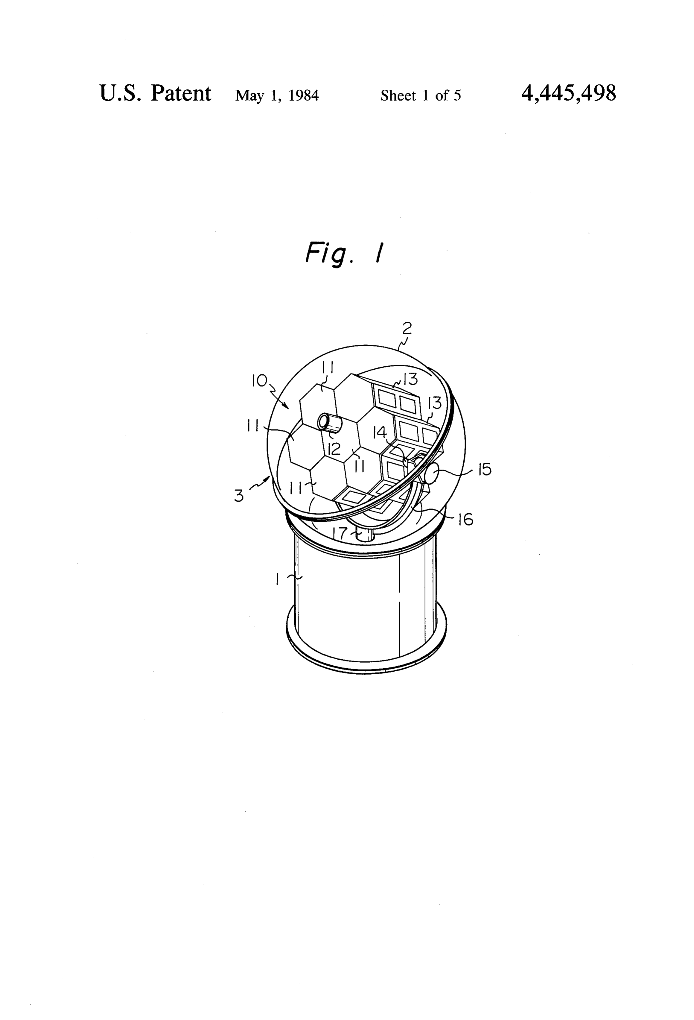
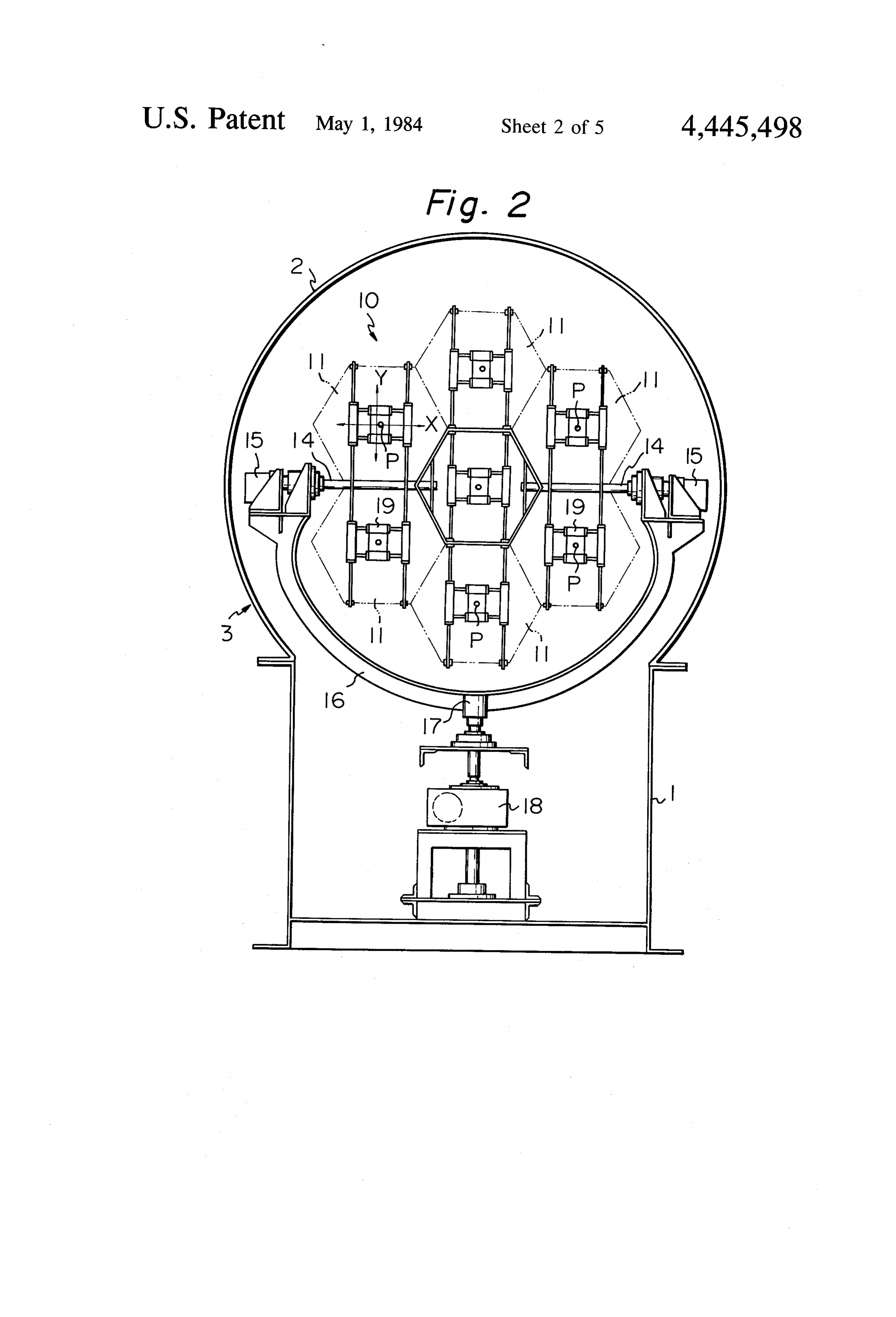
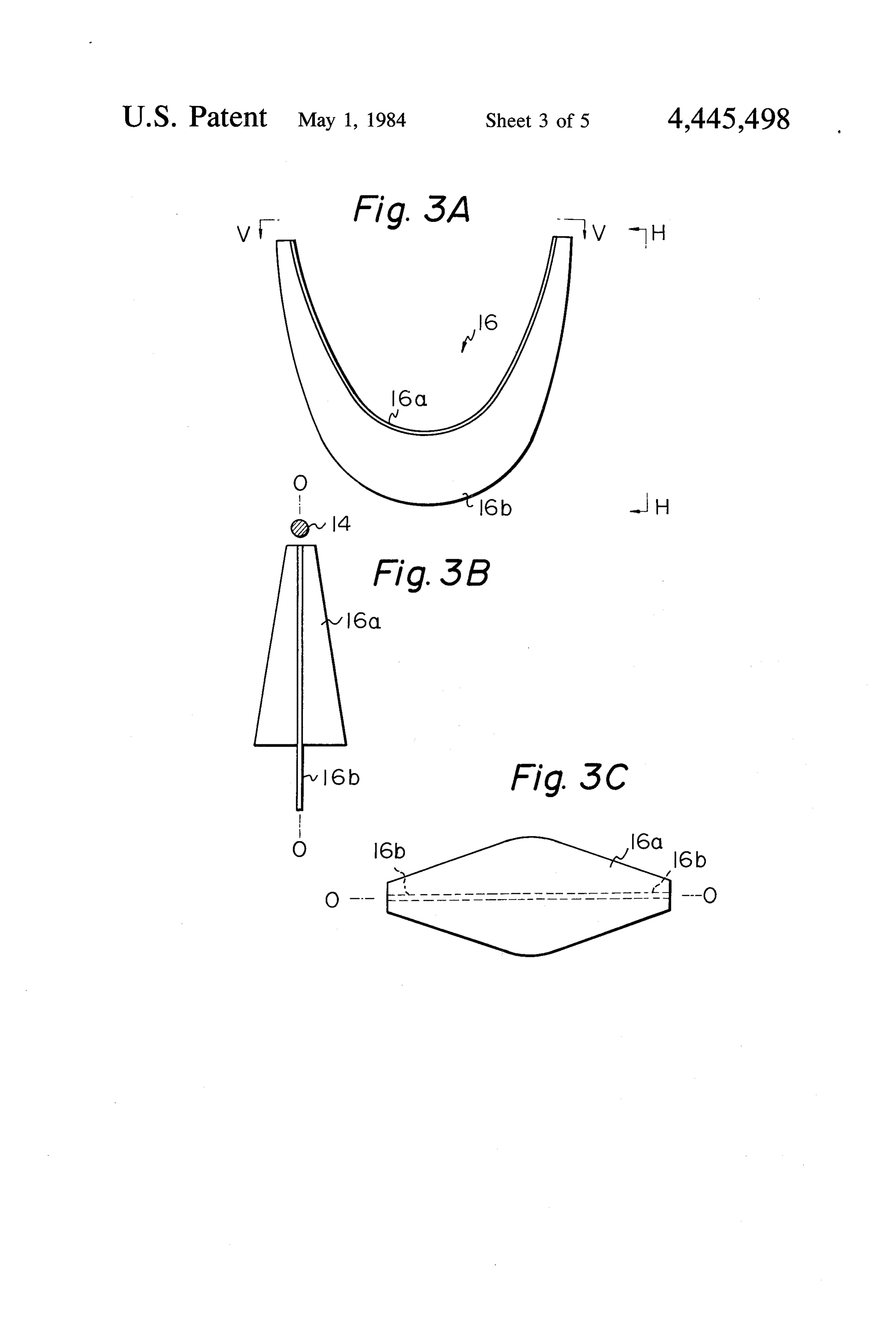
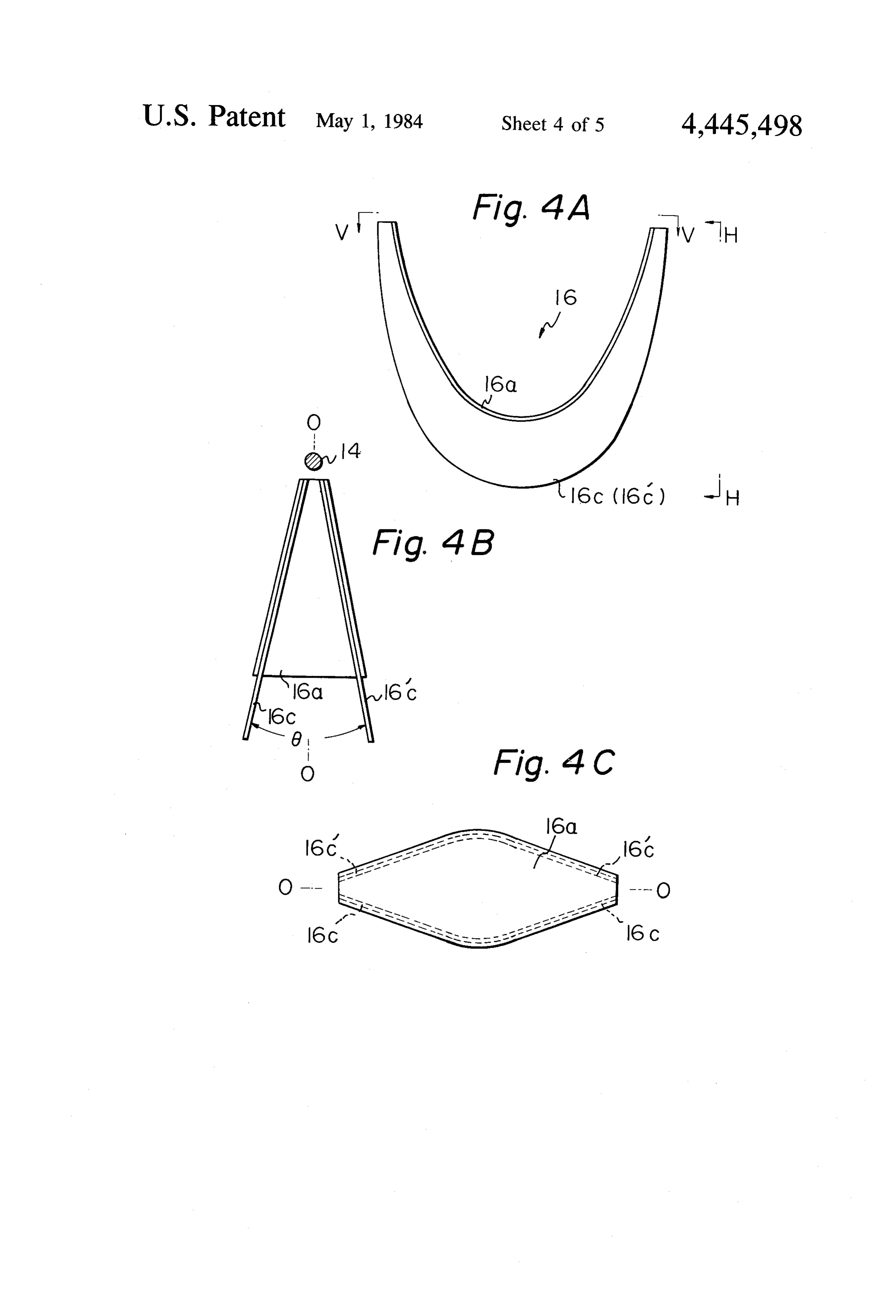
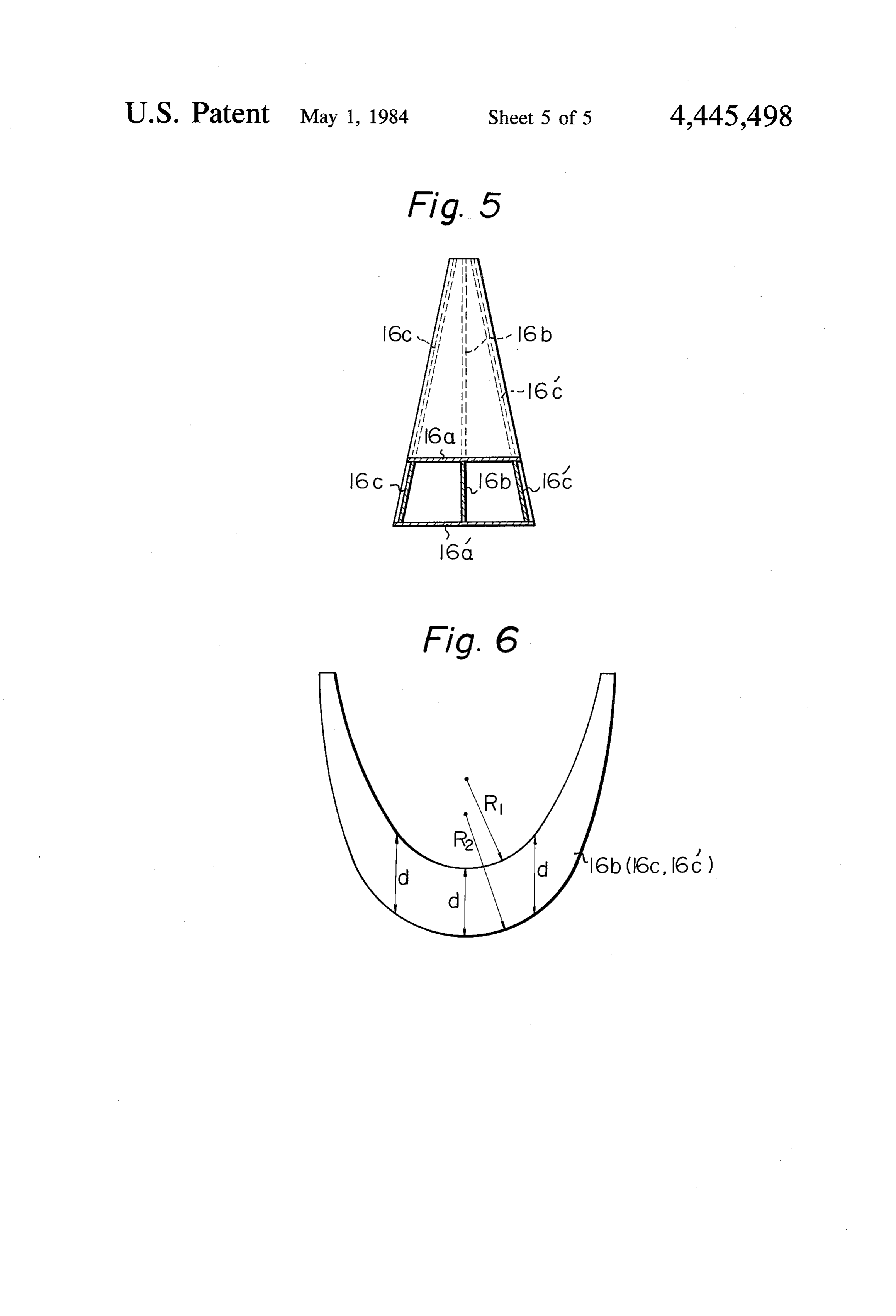
FIG. 3B is a side view taken along line H-H of FIG. FIG. 6 is a diagram to assist the explanation of the 3A; and FIG. 3C is a plan view taken along line V-V 20 shape of the second member shown in FIG. 3. of FIG. 3A.
Page 2drawing sheetscan →
Page 3drawing sheetscan →
Page 4drawing sheetscan →
Page 5drawing sheetscan →
Page 6drawing sheetscan →
Page 7scan →
SUPPORT ARM FOR A SUNLIGHT FIG. 2 is an enlarged rear view of the sunlight con centrating and collecting apparatus shown in FIG. 1;
CONCENTRATING AND COLLECTING FIGS. 3A, 3B, and 3C are drawings illustrating one APPARATUS embodiment of the support arm for a sunlight concen trating and collecting apparatus according to the pres
FIELD OF THE INVENTION ent invention, in which FIG. 3A is a front view, FIG. The present invention relates to the utilization of 3B is a side view taken along line H-H of FIG. 3A, and Solar energy. More particularly, the present invention FIG. 3C is a plan view taken along line V-V of FIG. relates to a support arm suitable for a large-size sunlight 10 3A;
concentrating and collecting apparatus. FIGS. 4A, 4B, and 4C are drawings illustrating an other embodiment of the support arm according to the
SUMMARY OF THE INVENTION present invention, in which FIG. 4A is a front view, Many technical ideas have been proposed for the use FIG. 4B is a side view taken along line H-H of FIG. of solar energy as a source of illumination or electricity. 15 4A, and FIG. 4C is a plan view taken along line V-V One group of ideas call for sunlight to be concentrated of FIG. 4A;
by means of a lens or the like and then to be guided into therFIG. 5 is a sectional side elevation illustrating a fur embodiment of the support arm according to the a light conductor cable for transmission to another loca present invention;
tion for illumination or the like.
To effectively guide the sunlight into the light con 20 FIG. 6 is a diagram to assist the explanation of the ductor cable, it is necessary to control a light receiving inshape of the second member of the support arm shown plane of the lens to continuously and precisely track the sun's movement. For this purpose, in the prior sunlight DETAILED DESCRIPTION OF THE concentrating and collecting apparatus, the lens is INVENTION mounted so as to be rotatable around two perpendicu 25 FIG. 1 is a general perspective view showing one larly intersecting axes. One axis is the horizontal axis of embodiment of a sunlight concentrating and collecting a first rotatable shaft. The other axis is the vertical axis of a second rotatable shaft. In a sunlight concentrating presentapparatus to which a support arm according to the and collecting apparatus previously proposed by the view of invention is applied. FIG. 2 is an enlarged rear same applicant as this invention, the lens is fixed on the ratus shown in FIG.concentrating and collecting appa first rotatable shaft. The ends of the first rotatable shaft Referring to FIGS. 1 and 2, there is shown a capsule are supported by a single support arm, which in turn is 3 comprised of a hollow cylindrical base member 1 and supported by the second rotatable shaft. a transparent head portion 2 formed in the shape of a In modern large-sized sunlight concentrating and 35 sphere collecting apparatuses, a large numbers of lenses is pref. use, theorcapsule dome and mounted on the base member 1. In 3 encloses a sunlight concentrating and erable. The increased number of lenses, however, in collecting apparatus 10 therewithin. creases the load applied to the support arm. To bear this The apparatus 10 includes a plurality of lenses 11, increased load, the support arm must be made stronger e.g., 7 or 19 in number, integrally connected with each and thus becomes heavier. This presents a problem in other for concentrating sunlight; a solar direction sen that the gyrating mass of the support arm must be mini sor 12 for detecting the sun's position; holding frames 13 mized to ensure quick and smooth operation of tracking integrally holding the lenses 11 and solar direction sen the sun's movement. sor 12; a first rotatable shaft (horizontal shaft) 14 for The invention as claimed is intended to overcome the turning holding frames 13; first electric motors 15 for aforementioned defect of the prior technique. Accord 45 driving the first rotatable shaft 14; a support arm 16 for ing to the present invention, there is provided a first supporting the lenses 11, solar direction sensor 12, hold member having a curved plate formed substantially in ing frames 13, first rotatable shaft 14, and first electric the shape of circular arc and a second member having motors 15; a second rotatable shaft (vertical shaft) 17 an inverted saddle-shaped plate or plates. Said second disposed perpendicular to the first rotatable shaft 14; member is firmly fixed along the outer surface of said 50 and a second electric motor 18 (see FIG. 2) for driving first member. It lies on at least one plane containing the the second rotatable shaft 17.
axis of the first rotatable shaft and is symmetrical with In operation, the solar direction sensor 12 detects the respect to the neutral plane of said first member. sun's position. The output signals are used to control the The advantages offered by the present invention are first and second motors 15 and 18 as keep the lenses 11 that the apparatus can be constructed to be light in 55 continuously tracking the sun's movement. weight and large in mechanical strength in both the The sunlight concentrated by lenses 11 is introduced vertical and horizontal directions. Thus, the apparatus into light conductor cables (not shown) or the like can track the sun's movement rapidly and smoothly. whose inlet ends are disposed at the focal points of each BRIEF DESCRIPTION OF THE DRAWENGS of the lenses 11. The sunlight is then propagated through the light conductor cables to any desired place,
The invention will be more fully understood from the for example, to a place where illumination is desired. following detailed description taken in conjunction In FIG. 2, reference numerals 19 indicate adjusting with the accompanying drawings, in which: means for keeping the light receiving ends of the light FIG. 1 is a general perspective view diagrammati conductor cables at the focal points of the lenses 11. In cally illustrating the structure of one embodiment of a 65 practice, the light receiving ends of the light conductor sunlight concentrating and collecting apparatus to cables are fixed to the points P of the adjusting means which a support arm according to the present invention 19. For adjustment the above adjusting means 19 can be is applied; moved in the X and Y directions to bring the light 8 receiving ends of the light conductor cables to the focal by support arm 16 at a well balanced condition during points of the lenses 11. turning.
In the above-mentioned sunlight concentrating and As for the horizontal load applied to the first rotat collecting apparatus, the increased number of lens also able shaft 14 in the lateral direction to the axis thereof, increases the vertical and horizontal loads applied to the as particularly shown in FIG. 4, said horizontal load can support arm 16. Thus, support arm 16 must also be effectively be supported by the two second members strengthened and thus increased in weight to support 16c and 16c. In such a case, the larger the angle e this increased vertical and horizontal loads. On the between the second members 16c and 16c', the larger other hand, since the support arm 16 is rotated by the 10 the mechanical strength of the support arm 16. motor 18 through the second rotatable shaft 17, the FIG. 5 is a sectional side elevation illustrating a fur gyrating mass of the support arm 16 must be reduced as ther embodiment of the support arm, wherein the sup port arm is provided with a further first member 16a much as possible to ensure quick and smooth operation outside of the original first member 16a. In this embodi of automatic tracking of the sun's movement.
Under such background the present applicant made 15 ment, the two first members 16a and 16a' are firmly connected by above-mentioned second members 16b, researches and completed the present invention. 16c, and 6c'. It will easily be understood that the sec FIG. 3A is a front view showing one embodiment of ond the support arm 16 according to the present invention; tivelymember 16b or members 16c and 16c' may be selec employed for this purpose.
FIG. 3B is a side view taken along line H-H of FIG. FIG. 6 is a diagram to assist the explanation of the 3A; and FIG. 3C is a plan view taken along line V-V 20 shape of the second member shown in FIG. 3. of FIG. 3A.
As shown in FIG. 3A, the support arm 16 is con portion is larger than that of thetheendwidth As mentioned previously, of the middle structed with a first member 16a having a curved plate the lengths d, d . . . measured in the verticalHowever, portions.
direction formed substantially in the shape of circular arc and a second member 16b having an inverted saddle-shaped 25 are substantially equal. In the embodiment shown in FIG. 6, the radius R2 of the outer contour is larger than plate. The second member 16b is firmly fixed along the the radius R1 of the inner contour. However, these outer or convexed surface of the first member 16a by contours can be designed as R = R2 (centers of two any suitable means, for example, by welding and lies on contours are offset with each other) or as R2d R1 (cen the plane containing the axis of the first rotatable shaft ters of two contours are registered with each other). 14 and also passes through the neutral plane O-O of 30 As will readily be understood from the foregoing the first member 16a, description, according to the present invention, even FIG. 4A is a front view showing another embodi when large vertical and horizontal loads are applied to ment of the support arm 16 according to the present the support arm, since the second member or members invention; FIG. 4B is a side view taken along line H-H are disposed in a symmetrical relation with respect to of FIG. 4A; and FIG. 4C is a plan view taken along line 35 the neutral plane of the first member, these loads can V- V of FIG. 4A. effectively be supported of the first member, these loads In FIG, 4, the support arm 16 is provided with two can effectively be supported by the support arm. Fur second members 16c and 16c'. In another embodiment, thermore, there can be provided a sunlight concentrat the second members 16c and 16c' lie on two different ing and collecting apparatus which is constructed to be planes containing the axis of the first rotatable shaft 14. light in weight and large in mechanical strength in both They also pass through planes which are symmetrical the vertical and horizontal directions and which can with respect to the neutral plane O-O of the first mem track the sun's movement rapidly.
ber 16a. The invention has been described in detail with refer In such a case, formation of the first member 16a to ence to preferred embodiments thereof, but it will be have side surfaces coinciding with planes containing the 45 understood that reasonable variations and modifications axis of the first rotatable shaft 14 and then firmly fixing are possible without departing from the spirit and scope the second members 16c and 16c' aligned with said side of the invention. For example, if some increase in mass surfaces will automatically position the second mem is allowable, the first member 16a of the support arm 16 bers 16c and 16c' at the above-mentioned relations. This can be made a rectangular shaped plate having a uni facilitates the positioning of the second members 16c 50 form width over the entire length thereof. and 16c' along the planes and enables easy manufactur I claim:
ing of the support arm 16. 1. A support arm for a sunlight concentrating and As shown in FIGS. 3A and 4A, the first member 16a collecting apparatus, said apparatus enclosing a plural is formed so that the width thereof becomes narrower ity of lenses integrally connected with each other, light from the middle to the ends. 55 conductor cables having light receiving ends thereof With the above-mentioned construction, the vertical arranged at each focal point of said lenses, a first rotat load applied to the first rotatable shaft 14 can be sup able shaft for turning said integrated lenses around the ported by the second member 16b or the second mem horizontal axis, a support arm for rotatably supporting bers 16c and 16c'. Thus, the mechanical strength per the ends of said first rotatable shaft, and a second rotat unit length of the second member or members becomes 60 able shaft for turning said support arm around the verti uniform over the entire length thereof. This allows the cal axis perpendicular to said horizontal axis, whereby required area of the second member or members, i.e., the turning of said first and second shafts is controlled the mass thereof, to be minimized. to cause said lenses to face the position of the sun so as Since the second member 16b or members 16c and to collect sunlight into said light conductor cables, 16c' lie on each plane containing the axis of first rotat 65 characterized in that said support arm comprises a first able shaft 14 and are symmetrical with respect to the member having a curved plate formed substantially in neutral plane O-O of first member 16a, the vertical the shape of circular arc, a second member having an load applied to first rotatable shaft 14 may be supported inverted saddle-shaped plate or plates, said second 9 member being firmly fixed along the outer surface of 5. A support arm as claimed in claim 1, in which the said first member, and lies on at least one plane containcontour of said second member is constructed by two eccentric circles with different radii.
ing the axis of first rotatable shaft and is symmetrical 6. A support arm as claimed in any one of claims 1 with respect to the neutral plane of said first member. through 5, in which the width of the middle portion of 2. A support arm as claimed in claim 1, in which the said first member is larger than that of the end portions. width of the middle portion of said second member is first 7. A support arm as claimed in claim 6, in which said member is formed so that both side surfaces coin larger than that of the end portions, cide with planes containing the axis of the first rotatable 3. A support arm as claimed in claim 1, in which the O shaft.
contour of said second member is constructed by two 8. A support arm as claimed in any one of claims 1 eccentric circles with the same radii. through 5, further comprising another first member 4. A support arm as claimed in claim 1, in which the outside of and spaced from said original first member at a predetermined distance, said other first member being contour of said second member is constructed by two 5 firmly fixed to said second member or members. concentric circles with different radii.
Provenance
- Collection
- Patents citing this work
- Pages
- 9
- Method
- pdftotext (the PDF's own text layer) + pdftoppm 300dpi page scans
- Patent office record
- patents.google.com →
- Source
- Google Patents citing-documents table
- Assignee
- Kei Mori
- Published
- 1984-05-01
- Transcribed from
- patentimages.storage.googleapis.com →