

patent · US4354348A
Solar space vehicle
19 October 1982
Text
Page 1scan →
United States Patent (19)
(54). solar space vehicle
76) Inventor: Robert E. Lee, 479 Dean St.,
Brooklyn, N.Y. 11217
52 U.S. C. ................................ 60/203.1; 60/641.15;
1,599,481 9/1926 Marcuse .............................. 126/271 3,064,418 11/1962 Sanders ..... ... 60/203 3,064,418 11/1962 Sanders ......... ... 60/203 3,152,260. 10/1964 Cummings .... ... 60/641 3,680,307 8/1972 Michalec ............................... 60/641
3,825,211 7/1974 Minovitch............................. 60/203 3,965,683 6/1976 Dix ..... 126/271 X 3,987,780 10/1976 Nozik ..... ... 126/271 4,043,315 8/1977 Cooper ... ... 126/271 X 4,056,093 11/1977 Barger ............................ 126/440 X 4,057,048 11/1977 Maine .................................. 126/440 4,068,474 1/1978 Dimitroff ... ... 60/641 4,136,670 1/1979 Davis .................................. 126/271 Primary Examiner-Allen M. Ostrager
This invention relates to space vehicle where solar en ergy is used to generate steam, which in turn, propels the vehicle in space. A copper boiler is provided and a novel solar radiation condensing means is used to focus the sunlight on said boiler. Steam generated in said boiler is exhausted to the environment to provide a thrust for the vehicle.
1 Claim, 3 Drawing Figures
Drawings
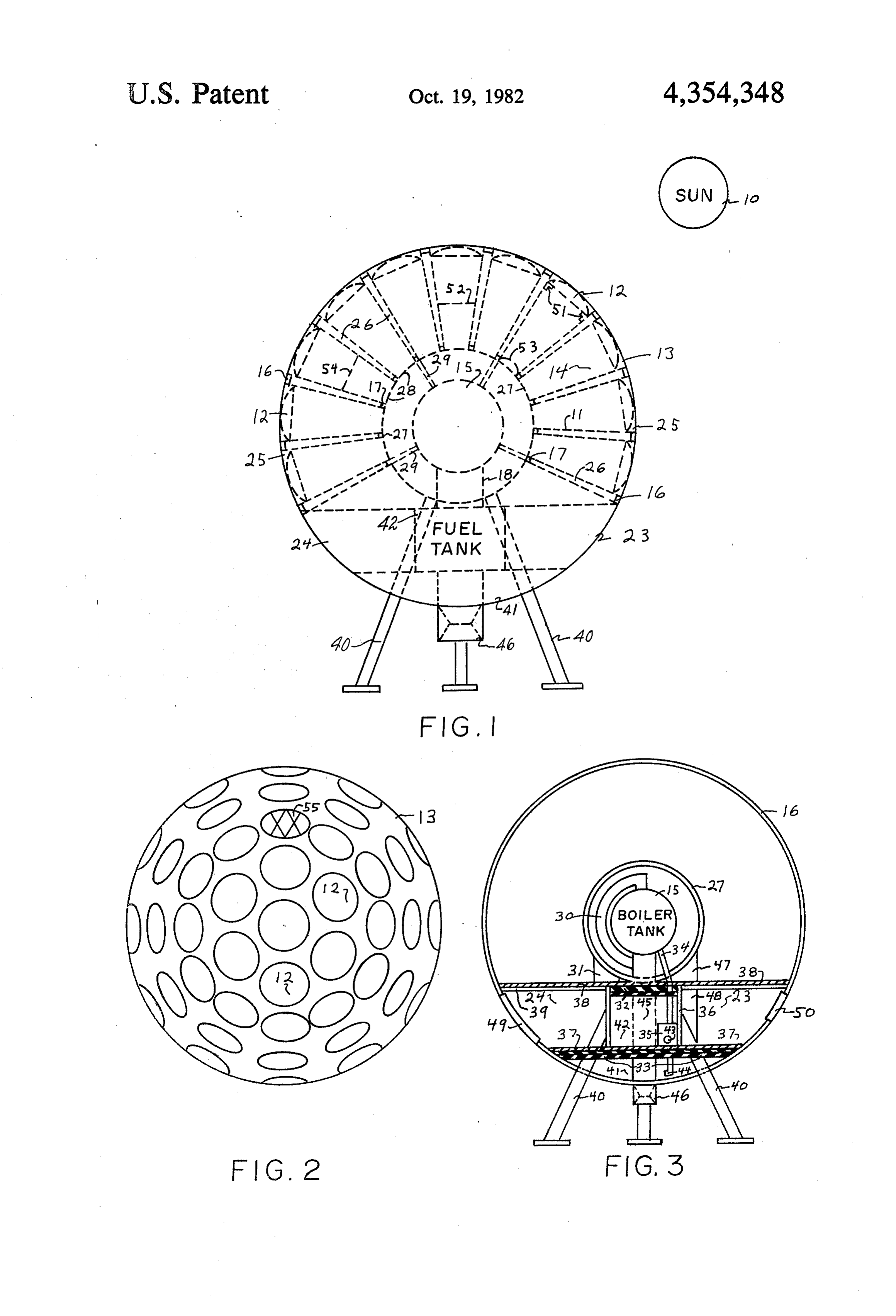
FIG. 3 is a side sectional view of the vehicle showing theC2S. expansion of the liquid including a pressure release the boiler tank, fuel tanks, passenger and control com Further modifications could permit a gas to be used in partments.
Page 2drawing sheetscan →
Page 3scan →
Solar radiation 10 passes through lenses 12 which are
SOLAR SPACE VEHICLE secured by brackets 51 to the tube means 14. The solar radiation strikes the sides of the tapered tubes and then
This invention relates to a solar space vehicle and passes to the boiler. tank 15 to heat the fuel in the said means to effect a thrust to propel the vehicle in air, 5 tank 15. Tube means 14 angularly disposed within the outer space, and for other various vehicles and uses. An fuselage 13 and the enside encasement 27, and suitably object of this invention is a provision of a means of aligned to focus the radiation on the boiler tank give up transportation in the air to all parts of the world. electrons to the radiation stream. The inside at 11 of the This application is related to patent application-ti tapered tubes 14 are coated with a suitable metal that tled Solar Hydrogen Engine, Ser. No. 697,213, filed O gives electrons to the said radiation stream. The said Aug. 13, 1976, now abandoned. metal may be tourmaline gem stone granules with a A further object of this invention is to provide a suitable cement. Other semiconductor materials and means for traversing long distances without refueling. arrangements may be used. Platinum nickel screens 52 The invention has also for its object to provide a may be secured in the tubes 14 as a thermo-couple to military vehicle for whatever purpose it may be re 15 supply some electric current for the vehicle. Tubes 14 quired. may be modified and used as a vacuum tube with a Still additional benefits and advantages of this inven quartz lens or window at 53 to transfer the emitted tion will become evident from a study of the following radiation to the boiler tank 15. Also an emulsion liquid detailed description taken in conjunction with the ac or gelatin may be used in the said tubes, such as potas companying drawings in which: 20,
FIG. 1 is an aft end sectional in part view showing trons sium chromium tartrate which will transfer more elec tubes radially positioned around the boiler tank with tank 15. through the quartz window 53 to heat the boiler lenses mounted in the tubes in dash line representation. also produce Sulfuric acid mixed with sodium chloride will FIG.2 is a top plan view of the invention showing the section of eachmore radiation for the radiation stream. A lenses suitably secured to the skin, or fuselage of the in the fluid containeris modified 25 tube with an aperture to slide and also making allowances for vehicle.
FIG. 3 is a side sectional view of the vehicle showing theC2S. expansion of the liquid including a pressure release the boiler tank, fuel tanks, passenger and control com Further modifications could permit a gas to be used in partments.
Describing the invention more in detail in its broader 30 the tubes in which each tube would be modified to aspects, the said invention comprises a vehicle of sev contain a suitable gas to transfer the radiation to the eral shapes and sizes but shown here with a spherical boiler tank. Sodium vapor could be used with silicon fuselage, consisting of a suitable perforated titanium coated on the inside of the tubes. Many modifications skin 13 which permits apertures 25 to allow solar radia and arrangements could be made to improve the radia tion 10 to steam boiler tank 15. 35 tion stream. The said tubes 14 can also be modified by Preferably the space vehicle skin structure 13 is made sliding or turning two tubes, one within the other, to of titanium or an alloy of titanium to provide a strong provide focusing adjustment for the radiation stream. and stable support for the vehicle at various speeds. Preferably a telephoto lens system is used to condense Latitude ring ribs 16 arrranged and secured within the the radiation on the target or boiler tank or other associ sphere vehicle support the fuselage. Angularly posi ated arrangement to suitably focus the radiation on the tioned conical tubes or pipe supports 26 are welded to said target or tank 15. The stated modifications are not latitude ring ribs 16 and inside ring ribs 17 which are shown but are applicable to this invention. welded to inside encasement 27. Supports 29 secured in Solar radiation 10 or other radiation passes through selected angular positions are welded to inside encase the transparent lenses 12 and through the tubes 14 ment 27 and are suitably secured to the copper tank 15 45 which are coated with a material that gives up electrons by welding or other means, and serve to help stabilize or other particles to the radiation stream which passes the entire structure of the vehicle. Transverse ribs 39 through aperture 28 to the target or boiler tank 15. and support plate 38, and circular bulkhead 36 are , Abutterfly type damper valve or a shutte means to welded together and provide transverse and vertical control the amount of radiation to the target or boiler 15 support for the vehicle and also form control and pas 50 should be used in each tube and is shown in dashed line senger compartments 24 and 23. Deck plate 37 is representation at 54. In this invention the lenses and welded to circular bulkhead 36, ribs 16, and support tubes are illustrated as being suitably focused on the legs 40, which also partitions and forms, and arranges copper tank 15. Water or an alkali metal from fuel tanks fuel tanks 41 and 42. Nitrogen from tank 31 pressurizes 41 and 42 are forced into the boiler tank 15 by expand expandable bladders 32 and 33 to force the fuel through 55 able pressure bladders 32 and 33 which are pressurized inlets 43 and 44 into the pump 35 and through pipe 34 to by nitrogen pressure from nitrogen tank 31. The fuel is the boiler. The fuel is preheated by the combustion tube forced from the said tanks 41 and 42 and through pipes 45 which is made applicable to suitably transfer heat by 43 and 44 to the pump 35, which assists the bladders 32 convection to the fuel. and 33 and pumps the fuel to the boiler tank 15. The fuel The fuel is preferably steam or an alkali metal for the is heated to a vapor in the boiler tank 15. The expanded propellant. The water or alkali metal is heated to a gases are forced out pipe channel 30 to thrust channel vapor in the boiler tank 15. The expanded gases effect 45 and out convergent-divergent nozzle 46. Preferably the thrust of the vehicle and exchanges momentum with the vehicle is an air breather with a suitable compressor the environment to produce the lift of the vehicle. The to compress the gases to effect a suitable thrust and control units for the fuel control and navigation control 65 effect the lift of the said vehicle in proportion to the size panels and other equipment are shown in enclosures 47 of the craft. The air ducts for the air and the compressor and 48. Wings, rudder, ailerons, and other aerodynamic arrangement are not shown but are necessary to provide parts are not shown on the vehicle. an effective thrust.
Page 4scan →
Lenses 12 may be facetted to focus more radiation on b. a smaller diameter spherical copper boiler located the target or boiler 15. The facets are shown at 55. inside and at the approximate center of said outer Boiler tank 15 may be modified in construction by sphere;
securing a section of zinc metal over one forth part of c. means for delivering water to the interior of said the lower half of the copper tank 15 which would sup copper boiler;
ply some electric current to the battery or other se d. means for exposing said copper boiler to solar lected equipment. One door is shown at 49 and one radiation and to a flow of electrical charges window at 50. Pivotable wings for vertical and horizon whereby steam is generated, in said boiler; tal flights are necessary for effective flight of the space e. means for delivering said generated steam from the vehicle, in which the mechanics of pivotable wings are 10 boiler to the environment outside the outer sphere known, and not shown herein. Thrust tube 45 is also to thereby provide a thrust component and hence a secured in the horizontal position for the horizontal propulsion force for the vehicle; flight but not shown in the drawings. f, said means for exposing the boiler to solar radiation This invention, solar space vehicle, may be modified and said flow of electrical charges including; for use on sea-going ships, water craft, road vehicles 15 1. tapered cones mounted about the entire periph and other uses. With many possible configurations, and ery of the copper boiler, while this invention is described and illustrated herein, 2. said tapered cones having their narrow ends it is not proposed that this invention be limited to the adjacent said boiler and their wider ends eminat exact details of construction herein shown in the draw ing to openings in the outer sphere, ings and described in the specification and that reserva 20 3. lenses mounted in the wider ends of the tapered tions of the rights in practice are made, to the end that cones substantially contiguous with the outer any necessary changes and modifications may be made surface of the outer sphere, therein, which may come within the scope of this inven 4. tourmaline gem stones lining the side walls of tion. said cones whereby a piezoelectric effect is gen What I claim is: 25 erated upon solar energy impinging on the side 1. A space vehicle comprising: walls of the cones.
a. a large diameter outer sphere; s x k
Provenance
- Collection
- Patents citing this work
- Pages
- 4
- Method
- pdftotext (the PDF's own text layer) + pdftoppm 300dpi page scans
- Patent office record
- patents.google.com →
- Source
- Google Patents citing-documents table
- Assignee
- Lee Robert E
- Published
- 1982-10-19
- Transcribed from
- patentimages.storage.googleapis.com →