

patent · US4076025A
Solar steam boiler
28 February 1978
Text
Page 1scan →
United States Patent (19)
Parker
54). solar steam boiler
(76 Inventor: Louis W. Parker, 2040 N. Dixie
Highway, Fort Lauderdale, Fla.
51 Int. C.’................................................. F24, 3/02 52 U.S. C. .................................... 126/271; 126/270;
1,951,403 3/1934 Goddard .............................. 126/271 1969,839 8/1934 Goddard .............................. 126/271 2,872,915 2/1959 Bowen ................................. 126/271 2,920,710 1/1960 Howard ........................... 126/270 X 3,000,375 9/1961 Golay ................................... 126/270 3,919,998 11/1975 Parker .................................. 126/270
Foreign patent documents
1,141,261 8/1957 France ................................. 126/270 Primary Examiner-Kenneth W. Sprague
Assistant Examiner-Larry Jones
Attorney, Agent, or Firm-Pollock, Vande Sande and
Priddy
A solar heater comprising two or more containers nested one within the other for the solar heating of a gaseous medium such as air therein. Each container is provided, near its lower end, with a solar radiation absorbing metal sheet which, when it becomes hot, raises the temperature of the air within the container causing the heated air to rise to the top of the container where it transfers some of its heat to the adjacent con tainer and to the outside air, thereby creating convec tion currents. The innermost container is provided with a boiler structure positioned to be heated by incident solar radiation to a temperature sufficiently high to convert water within the boiler structure to stem. The boiler structure is of thin flat configuration, is covered by radiation absorbing material on the face thereof which is exposed to solar radiation, has its opposite face polished to a shine, has a number of reinforcing mem bers extending between the opposing faces of the boiler structure, and exhibits surface sections of smoothly curved outwardly bulging convex configuration be tween the reinforcing members to provide a compara tively light weight boiler structure having adequate strength to withstand the pressure of steam generated therein. In one form of the invention a cylindrical lens is provided to concentrate the sun's rays and superheat the steam obtained from the boiler.
6 Claims, 7 Drawing Figures
Drawings
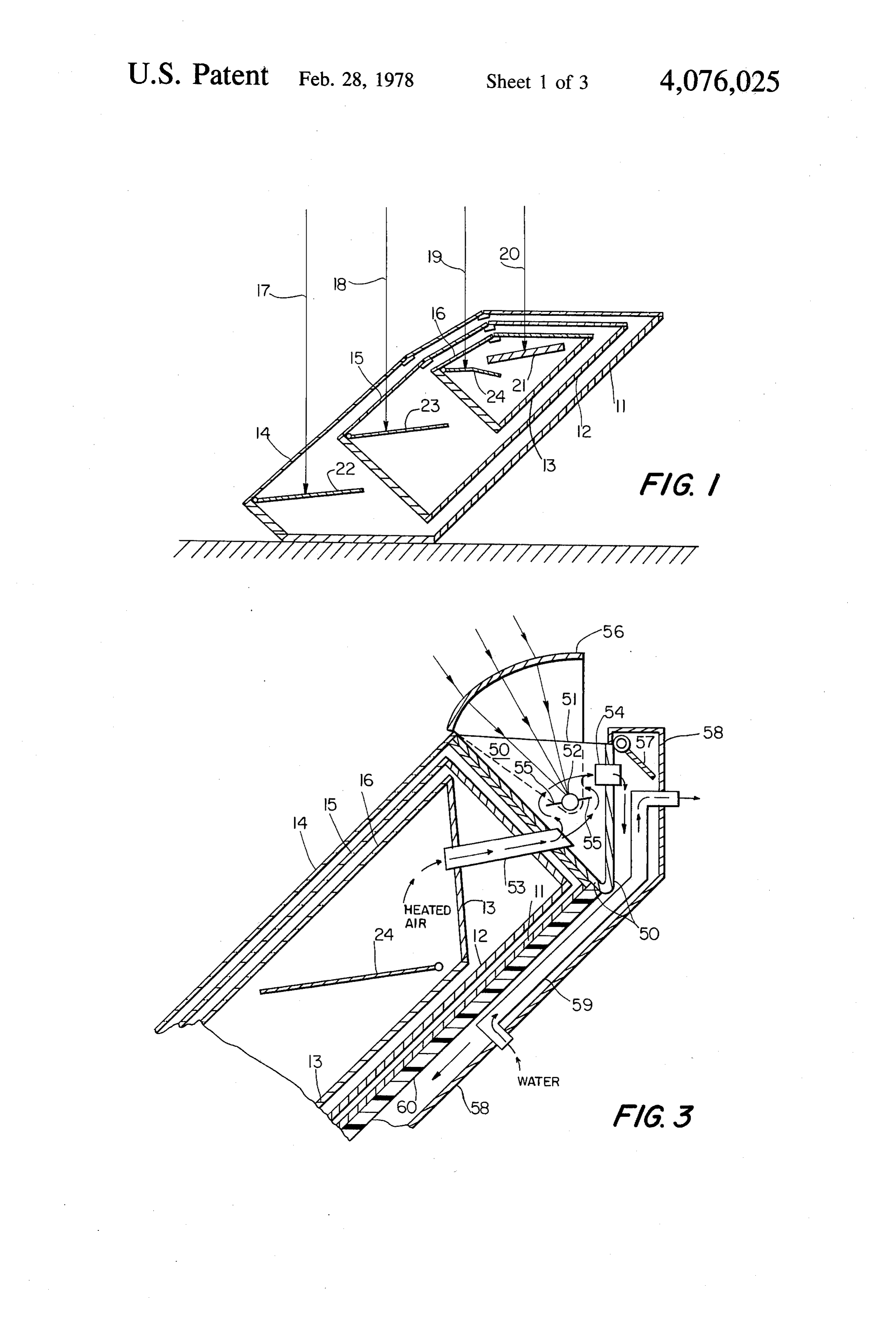
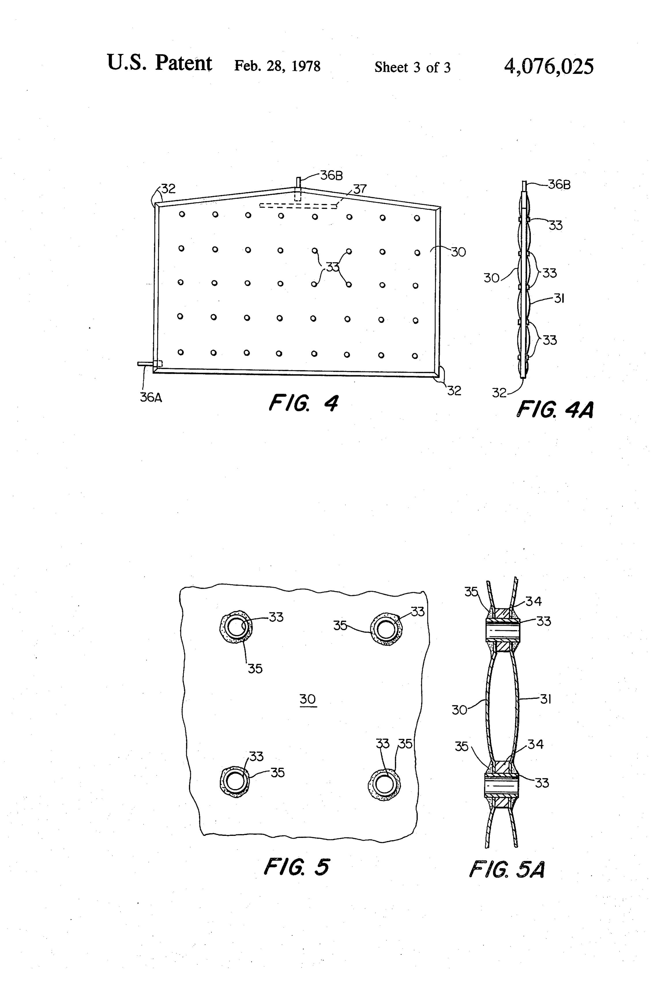
FIG. 1 is simple and inexpensive to build, but is never
Page 2drawing sheetscan →
Page 3scan →
Preheater
Transparent 2y4
Cover
Valves
- - - - - - - -f - - - -- an are u- a -- a-- a -- a -
Optional reserve
Page 4drawing sheetscan →
Page 5scan →
solar heating systems of the general type described in
SOLAR STEAM BOLER my aforesaid prior patent.
BACKGROUND OF THE INVENTION SUMMARY OF THE INVENTION The present invention is concerned with improved 5 In accordance with the present invention, a solar solar heaters of the general type described in my prior heating system comprises two or more containers U.S. Pat. No. 3,919,998 issued Nov. 18, 1975, for "Con which are housed within one another and which may vection-Type Solar Heating Unit". The solar heater of have their interiors in gaseous medium flow communi my said prior patent is based upon the principle that cation with one another as described in said prior patent radiated solar energy falling on an absorbing body, e.g., 10 or which, instead, have their respective interiors closed a steam boiler disposed within the solar heating unit, off and physically separated from one another in respect would heat the boiler to an extremely high temperature to the flow of gaseous medium. One or more heat ab if the boiler did not lose heat by re-radiation and con sorbing and radiating plates are located near the lower duction. Such conduction and re-radiation is effectively end of each container to set up convection currents of minimized by so arranging various surfaces in the solar 15 the air or other gaseous medium within each of said heater that they radiate less than they absorb, and the containers. In accordance with one of the improve conduction loss which would otherwise occur is elimi ments of the present invention, the opposite sides of said nated by the use of solar radiation absorbing sheets that plates are coated with different materials to cause the heat the air surrounding the boiler to a temperature as top side of each plate to absorb more heat than it will high as or higher than the temperature of the heated 20 radiate while the backside of each plate transmits its boiler. heat to the surrounding gaseous mixtures in each con Since the basic structural considerations which tainer.
should be embodied in a solar heater achieving these A steam boiler, exposed to solar radiation, is disposed results are fully described in my said prior U.S. Pat. No. within the innermost container and, in accordance with 3,919,998, the disclosure of said prior patent is incorpo 25 another of the improvements of the present invention, rated herein by reference. Briefly, the solar heating unit the side of said boiler which faces the incident solar comprises a plurality of containers, i.e., two or more radiation is coated with a heat absorbing material while containers, nested one within the other with each of said its opposite side is polished to a shine thereby to in containers having a gaseous medium, e.g., air therein. crease heat absorption by, and to reduce heat radiation The containers respectively have transparent upper 30 from, the boiler. In accordance with a still further im surfaces which are superposed and positioned to admit provement of the present invention, moreover, the solar solar radiation to each of said containers. In addition heater may be provided with a lens arrangement which each container houses one or more solar radiation ab operates automatically to focus or concentrate solar sorbing sheets which transfer heat to the gaseous me energy onto the pipe or conduits carrying the steam dium within the container. Various different other sur 35 generated by the boiler. The lens arrangement and asso faces of the containers are coated with heat insulating ciated conduits are preferably constructed as an integral and with heat reflective materials. The heat radiating part of the solar heater, are located at upper end of the sheets are so arranged that convection currents are solar heater, and function to superheat the steam ob produced in the gaseous medium within the containers tained from the boiler.
thereby to cause the temperature of the gaseous medium The present invention also provides a comparatively in the innermost container to be raised to a temperature low cost solar steam boiler suitable for heating by solar which converts water to steam, and a steam boiler radiation and capable of withstanding a steam pressure structure is provided within the innermost container to in the order of 20 pounds per square inch. The solar achieve this conversion. steam boiler exhibits higher efficiency than prior art As discussed in my prior patent, the overall efficiency 45 devices inasmuch as the entire surface of the boiler is of a solar heating system is measured by the heat units nearly flat and is substantially completely covered with (BTU's) obtainable per dollar invested, and in evaluat water on its interior, in contrast to conventional flat ing the comparative efficiencies of solar heating sys plate solar collectors which use spaced tubing sections tems, therefore, the most practical system becomes one exposed to the sun for heating water within the tubing. that generates the greatest useful energy output per 50 The boiler structure comprises a pair of compara dollar invested. A primary purpose of my prior pa tively large area metallic sheets which are disposed in tented invention was, accordingly, to provide a solar spaced, substantially parallel, comparatively closely heating system which made use throughout of compara adjacent relation to one another, said pair of metallic tively inexpensive components and which, moreover, sheets being maintained in this configuration by substan permitted the elimination of auxiliary devices that 55 tially U-shaped strips which overlie the edges of the would increase the cost of the solar heating unit. These metallic sheets and which join corresponding edges of cost considerations are equally relevant in respect to the those sheets to one another. The boiler is further char steam boiler itself, for the use of a boiler configuration acterized by an array of spaced reinforcing members, which is expensive to construct would reduce the over preferably disposed in a substantially rectangular array, all efficiency of the heating system. Nevertheless, the 60 which extend between the metallic sheets at a plurality boiler structure must be of such configuration that it is of spaced locations inward of the edges of said sheets. adapted for incorporation into a solar heating system of Each of the reinforcing members is of elongated config the type described, and exhibits adequate strength to uration, is disposed at substantially right angles to the resist the very significant internal pressures which are planes of the sheets, and is attached to said sheets at the produced as steam is generated. The present invention 65 opposing ends of said reinforcing member. In a pre accomplishes these results and, in addition, provides a ferred embodiment of the invention, each reinforcing number of further improvements which individually member comprises a short metal pipe which is open and cooperatively improve the overall efficiency of throughout its length and at its opposingends, to permit 6 the passage of gaseous medium in the innermost con surfaces of the plural boxes ae covered with a heat tainer of the heater through the said hollow pipes from insulating compound, e.g., material of the type being one face to the other of the boiler. Such use of short marketed under the name "Gelcote' (neopenthyl gly pipes for reinforcing the boiler also provides greater col) on top of which is provided a layer of shiny alumi surface areas than would be provided by rivets to which 5 num foil. The upper surfaces 14, 15, 16 of the nested to solder together the sheets comprising the sides of the boxes are fabricated of a transparent material, e.g., glass boiler. plates, to permit the entry of solar radiation to each box, After the flat metallic sheets, their edge structures, the sun's rays being designated in FIG. 1 as 17, 18, 19 and the intervening pipe reinforcing members are as and 20. A steam boiler 21, acting as a heat absorbing sembled in the configuration described, steam or air 10 medium, is located near the top of the innermost box 13. under pressure is fed to the interior of the boiler to In addition, one or more heat absorbing metal plates 22, dilate or expand the metallic sheets at those portions 23, and 24 are provided in each of the boxes 11, 12, and thereof where they are not restrained by the reinforcing 13 near their respective lower ends. members. This operation causes each sheet of the boiler In operation, solar radiation enters the several boxes to assume a somewhat bubbly shape, which is main 15 through the transparent upper surfaces 14, 15, 16 to heat tained after the pressure is released, and which is char metal plates 22, 23, 24. These plates are covered with a acterized by adjacent, smoothly curved, outwardly selective absorber such as black copper oxide on the bulging, convex sheet sections. This dilating of the sheet sides thereof which are exposed to the sun's rays. The surfaces enlarges the capacity of the boiler very signifi reverse side of the plates 22, 23, 24 are also covered cantly and, in addition, causes the boiler to assume a 20 with a blackened material, except that the upper sides geometrical configuration which can withstand the contain a selective absorber coating such as copper greatest internal pressure of all possible geometrical oxide while the reverse or backside of each plate is shapes due to the fact that the internal pressure tends to covered with ordinary flat black paint. In this way, the subject the faces of the boiler to a tearing rather than a top side of each plate 22, 23, 24 will absorb heat directly bending force. 25 from the sun's rays, while the backside of each plate will
Brief description of the drawings
transmit its heat to the surrounding air. The heat ab sorbed and then radiated by plates 22, 23 and 24 is con
The foregoing objects, advantages, construction and ducted to the air within the boxes 11, 12 and 13, causing operation of the present invention will become more the air within each box to rise to the top of the box readily apparent from the following description and 30 where it is cooled slightly, thereby setting up convec accompanying drawings wherein: tion currents within each box. FIG. 1 is an illustrative side view of a basic solar Most of the energy which reaches boiler 21 takes the heater constructed in accordance with the present in form of direct solar radiation passing through transpar vention; ent surfaces 14, 15 and 16. Although boiler 21 receives FIG. 2 is a cross-sectional diagrammatic view of a 35 a very substantial amount of radiated heat, it would, in solar heater, of the type described in my prior patent the absence of other considerations, normally return No. 3,919,998, constituting an improved form of the most of that heat to the atmosphere by conduction and solar heater shown in FIG. 1; radiation. The separately heated air which surrounds FIG. 3 is a partial illustration of a solar heater of the boiler 21, however, prevents most of this conduction general type shown in FIG. 1 or FIG. 2, incorporating since the temperature of the air or other gaseous me a cylindrical lens arrangement for super-heating the dium adjacent the boiler is as high as, or higher than, the steam obtained from the boiler; surface of the boiler. The inside surfaces of the boxes 11, FIG. 4 is a plan view of an improved solar steam 12 and 13, being covered with shiny aluminum foil, boiler for use in the solar heaters of FIGS. 1-3; reflect radiated heat rays back to the boiler or back to FIG. 4A is an edge view of the solar steam boiler 45 metal plates 22, 23 and 24, so that the only area where shown in FIG. 4; heat radiation is lost is toward the transparent surfaces FIG. 5 is a detail view of a portion of one of the outer 14, 15 and 16. Moreover, boiler 21 is preferably covered surfaces of the solar steam boiler shown in FIG. 4; and on its topside with a selective coating such as black FIG. 5A is a detail cross-sectional view of the portion copper oxide, while its reverse side is polished to a of the solar steam boiler shown in FIG. 5. 50 shine; and heat radiation from the boiler is reduced by
Description of the preferred
the use of this shiny surface.
Embodiments
The general type of solar heater structure shown in
FIG. 1 is simple and inexpensive to build, but is never
FIG. 1 depicts the basic form of solar heating unit theless capable of raising the temperature of water in with which the present invention is concerned. The 55 steam boiler 21 to 212 For higher, generating steam. unit, which in a practical form is of elongated configu This is accomplished through use of the principle that ration, has a length on the order of 10 feet, is oriented at radiated solar energy falling on an absorbing body substantially 45 to the horizontal, and is constructed to would heat that body to an extremely high temperature produce interior convection currents of air or other if the absorber did not lose its heat by re-radiation and gaseous medium. conduction. The solar heater construction, as described, In the form shown in FIG. 1. (which differs from that reduces reradiation by use of selective surfaces that shown in my prior patent), the unit comprises three radiate less than they absorb, and reduces conduction independent, closed wooden boxes or containers 11, 12, loss from the boiler by preheating the air surrounding and 13 which are disposed in nested relation, one within the boiler to a temperature as high as or higher than that the other. While three boxes have been illustrated, the 65 of boiler 21.
principles of the present invention are equally applica An improved but more elaborate and expensive form ble to a solar heating unit which consists of only two, or of solar heater operating in accordance with the forego more than three, such boxes. The side wall and bottom ing general principles is illustrated in FIG. 2, and is 7 described in greater detail in my aforementioned prior transparent top plate 51 is covered with a black radia U.S. Pat. No. 3,919,998. Various elements in FIG. 2 tion absorbing substance, while the other side is pol which correspond to the elements already described in ished to shine.
reference to FIG. 1 have been designated by like nu A cylindrical Fresnel lens 56 is positioned outside of merals. transparent top plate 51 and is arranged to concentrate In the improved form illustrated in FIG. 2, the solar the sun's rays on pipe 52 thereby to increase the temper heater comprises a plurality of elongted containers or ature of, or superheat, the steam which is produced by boxes which, as in FIG. 1, are oriented at substantially boiler 21 (not shown in FIG. 3) as said steam passes 45 to the horizontal and nested within one another, from said boiler through pipe 52 for ultimate utilization. each container having a transparent upper surface posi 10 Lens 56 is adapted to be positionally adjusted by auto tioned to admit solar radiation to the container. In con matic means (not shown) to bring its focus onto pipe 52. trast to the independent box arrangement of FIG. 1, This adjustment may be effected by any well known however, the FIG. 2 arrangement is such that each means, such as that described by C. P. Gilmore in Popu container includes an inlet adjacent one end thereof for lar Science Magazine, October 1976, page 97, and there the admission of a gaseous medium, such as air or some 15 fore will not be specifically described here. other gas, to be heated by solar radiation within the A pipe 53 conducts hot air from container 13 into container, and further includes an outlet for the heated container gaseous medium adjacent its other end. The gas outlet 50 through50,aand the hot air thereafter leaves container further pipe 54 for circulation via con of each container is connected to the inlet of the next inner one of the nested containers, and the outlet of the 20 tainer end of 58 back to the gas inlet (not shown) at the lower outermost container 11 in the manner described innermost container is connected to the inlet of the outermost container, so that the gaseous medium flows from in my afore-mentioned prior patent. Fins 55 projecting continuously to and through each of the nested contain withineach side of steam pipe 52 keep the moving air container 50 from passing too near pipe 52, ers to cause the gaseous medium to be heated to succes which may sively higher temperatures as it flows through the con 25 coated with tend to cool said pipe. These fins are also a radiation absorbent material on both sides tainers in succession. The innermost container 13 can contain a thermocouple junction for the conversion of sharplythereof since the focal point of cylindrical lens 56 is not heat to electricity, but in the form shown in FIG. 2 alongsidedefined of and some of the focused energy rays fall pipe 52. A movable shutter 57 disposed contains boiler 21 operative to convert water fed to the boiler from a preheater to steam. This improved form of 30 adjacent the outer end of pipe 54 enables the air circula the invention is capable of producing higher tempera tion through the solar heater and through container 50 tures than the form shown in FIG. 1 but is more expen to be shut off at night thereby to prevent rapid loss of sive to produce. heat. Closure of shutter 57 in the evening causes the The foregoing comparative brief description is be water in boiler 21 to remain at a higher temperature for lieved to be adequate for purposes of understanding the 35 use the following morning.
FIG. 2 arrangement as well as the improvements to be Conduit 58, which conducts the hot air from the described hereinafter. A more detailed description is set outlet end of pipe 54 past the insulated bottom 60 of forth in my prior U.S. Pat. No. 3,919,998 which is incor container 11 to the gas inlet of container 11 for recircu porated herein by reference. lation, is made of metal to radiate the heat of the air It is well known that the cubic content of steam from within it. A water pipe 59 is located within container 58 a steam boiler can be increased substantially by heating so that the water therein is heated by the flow of heated the steam to a temperature well above the boiling point exhaust air surrounding it. This preheated water is used of water. Steam at these higher temperatures acts as an for replacement of the evaporated water in the boiler ideal gas, and accordingly doubles its cubic content at 21.
each 273 K. increase in temperature whereby greater 45 In order that the boiler 21 can receive the most radi energy can be extracted from it. Measurements indicate. ated energy per square inch, it is necessary that it have that the arrangement described in my prior U.S. Pat. a surface which is substantially flat. The cubic capacity No. 3,919,998 can generate 20 pounds of steam pressure of the boiler should, moreover, be comparatively low and a temperature of 260' F. It is possible, however, to due to the fact that solar radiation is available for only increase the temperature of the steam obtainable from 50 a few hours during the day, and during this time water my prior patented solar heater considerably higher by in the boiler has to be heated from a comparatively low use of a cylindrical Fresnel lens which concentrates the temperature to boiling in order to obtainsteam pressure. sun's rays on a pipe conducting the steam away from the These requirements dictate the use, in a solar heater of boiler. the type shown in FIGS. 1-3, of a thin flat boiler having FIG. 3 is a partial illustration of this improved form 55 the general configuration shown in FIGS. 4 and 4A. of the invention. In FIG. 3 the same numerals are used However a vessel having a thin flat shape tends to be as on the previous figures to identify like parts. Contain highly impractical since the vessel must withstand high ers 11, 12 and 13 serve the same purpose as before, but steam pressures. A boiler having a surface area of 40 only their upper ends are shown. At the upper end of inches by 50 inches, for example, must withstand an the nested containers 11-13, a further triangle-shaped 60 internal pressure of 40,000 pounds at a steam pressure of container 50 is provided which has a transparent top 20 pounds per square inch, which is the pressure in plate 51 as are employed in the other containers 11-13. tended in use. This ability to resist significant internal A steam pipe 52 connected to the outlet of boiler 21 (not pressures cannot be accomplished, as a practical matter, shown in FIG. 3) is disposed within container 50, said merely by the use of heavy materials having adequate pipe 52 extending transverse to the direction of elonga 65 strength, for such materials would raise the cost of the tion of containers 11-13, i.e., in a direction perpendicu boiler to a prohibitive extent particularly when it is lar to the plane of FIG. 3 whereby only its cross-section recognized that the boiler must be made of a compara is shown in the drawing. The side of pipe 52 which faces tively expensive non-corroding material such as copper.
Page 8scan →
The improved form of boiler shown in FIGS. 4, 4A, nal forces which seek to pull sheets 30, 31 apart when 5, and 5A exhibits the desired comparatively low cost, steam is generated in the boiler.
an ability to withstand steam pressures in the order of 20 A nipple 36a extends through the joined edges of pounds per square inch, and comparatively high effi sheets 30, 31 to permit the interior of the boiler structure ciency due to the fact that the entire surface of the to be filled with water or other working substance, and boiler is nearly flat and one of its sides is fully exposed a similar nipple 36b extends between the joined edges of to solar radiation and is completely covered with water the sheets in spaced relation to nipple 36a to provide a on its interior. These desirable results are achieved by steam outlet from the boiler structure. The interior of an arrangement wherein the surfaces of the boiler are of the boiler is, moreover, provided with a bar-shaped bubble shape, a configuration which has been found in 10 baffle 37 adjacent the steam outlet nipple 36b for inhibit practice to withstand the greatest pressure of all geo ing large bubbles of heated water from shooting into the steam outlet pipe 36b from the interior of the boiler metrical shapes, due to the fact that the material of the Structure, boiler is subjected to a tearing rather than to a bending force. In addition, the "bubbles' on the surface are so 15 When the boiler is first assembled in the general con arranged relative to one another that the overall surface figuration described above, the surfaces provided by exhibits a nearly flat configuration relative to solar radi sheets 30, 31 of the boiler are flat. After assembly, steam ation. The slight deviations in the surface from a 90' or air is fed into the boiler at a pressure of 20 pounds per square inch. This dilates the boiler causing it to assume incidence to the impinging rays is made small enough to represent a loss in the order of only one percent accord 20 the bubbly shape shown in FIG. 4A. The copper mate rial chosen for sheets 30, 31 permits the sheets to expand ing to Lambert's law. under pressure in the regions between the several rein FIG. 4 depicts the solar boiler from the side thereof forcements 33, and to maintain their resultant shape which is exposed to solar radiation, and FIG. 4A is an after pressure has been released. This dilation of the edge view of the structure shown in FIG. 4. The boiler sheet surfaces causes the boiler to substantially triple its comprises two comparatively large area metallic sheets 5 capacity.
30 and 31 which are interconnected to one another to form a closed vessel. Corresponding edges of the two pipes As will be noted in FIG. 4, the array of reinforcing 33 is a substantially rectangular array, but other sheets 30 and 31 are joined to one another by U-shaped configurations metallic strips 32 which are held in place by soldering. array is employed, can be chosen. When the rectangular In addition, the boiler is provided with a comparatively 30 causes the sheets 30theand dilation of the sheet surfaces large number of spaced reinforcing members 33 which curved, outwardly bulging,31convex to exhibit a smoothly configuration at extend between the sheets 30 and 31 at a plurality of each portion of the sheet which is bounded by four of spaced locations inward of the edges of said sheets, each said reinforcing member 33 being of elongated configu the reinforcing members 33 located respectively at the ration disposed at substantially right angles to the planes 35 corners of each rectangle in the rectangular array. This configuration is shown in detail in FIG. 5A. The resul of sheets 30 and 31, and being attached to said sheets at tant slight deviations from a truly flat surface, and from the opposing ends of each reinforcing member. a 90' incidence to the impinging solar rays, is suffi The reinforcing members 33 and their mode of at ciently small to represent a loss in the order of only 1% tachment to the sheets 30 and 31, is shown in detail in according to Lambert's law.
FIGS. 5 and 5A. Each reinforcing member consists of a 40 As a last operation, the side of the boiler which faces comparatively short metal pipe which penetrates the sun is blackened by application of either a suitable through both of sheets 30 and 31 via an annular member paint or a selective absorber, e.g., black copper oxide. or washer 34 which is disposed between sheets 30, 31 The other side of the boiler is polished to a shine so that and which has its opposing ends in engagement with the it will radiate less heat.
inner surfaces of said sheets respectively. The opposing 45 While I have thus described a preferred embodiment ends of each pipe or reinforcing member 33 are located of the present invention, many variations will be appar outwardly of the outer surfaces of sheets 30 and 31, as ent to those skilled in the art. The foregoing description best shown in FIG. 5A, and these outwardly extending is accordingly intended to be illustrative only and not ends of the pipes 33 are soldered to the outer surfaces of limitative of the present invention, and all such varia sheets 30 and 31 by solder joints consisting of substan 50 tions and modifications as are in accord with the princi tially annular bodies of solder 35. In order to withstand ples described are meant to fall within the scope of the the forces and temperatures which are encountered in appended claims.
practice, it has been found that the sheets 30 and 31 Having thus described my invention, I claim: should constitute copper sheets having a thickness of 1. A solar heater comprising a plurality of elongated substantially 0.040 inches, with the solder employed in 55 containers nested one within the other, each of said joints 35 being that available under the name "Silphos' containers having a gaseous medium therein, said con (an alloy of silver and phosphorus). However, other tainers respectively heaving transparent upper surfaces materials such as aluminum alloys may be employed for which are superposed and positioned to admit incident the sheets 30 and 31, and other suitable solders can also solar radiation to the interior of each of said containers, be employed. 60 the other surfaces of each container being coated with a The annuli 34 maintain a small gap (about inch) heat insulating material superposed by a heat reflective between sheets 30 and 31 adjacent each of the reinforc material for reflecting heat toward the interior of said ing pipes 33. Pipes 33, in turn, can comprise copper container, at least one heat absorbing and radiating plate pipes having a diameter of inch. By using components located within each of said containers adjacent one end of the types described, a comparatively large area sol 65 of said container, each of said plates having a face der joint 35 can be achieved, producing an excellent which is exposed to said incident solar radiation and bond between each pipe 33 and sheets 30, 31 which which is coated with a blackened material to cause said maintains high rigidity and a greater hold against inter plate to absorb heat from said incident solar radiation, 9 the opposite face of each such plate being coated with a heated by said incident solar radiation, the opposite face blackened material for transmitting heat from said plate of each such plate being coated with a blackened mate to said gaseous medium within said container to cause rial for transmitting heat to said gaseous medium within said gaseous medium to move in a convection current said container to cause said gaseous medium to move in toward the other end of said container, each of said a convection current toward the other end of said con nested containers being constructed to define an interior tainer, a steam boiler structure located within the inner volume which is completely closed off from the interior most one of said containers, said boiler structure being volumes of the others of said nested containers whereby positioned within said innermost container to be heated the convection current produced within each container by solar radiation incident on said boiler structure is confined to that container, and a steam boiler struc 10 through said superposed transparent surfaces, the exte ture located within the innermost one of said nested rior side containers, said boiler structure being positioned within incident solar of said boiler structure which is exposed to said innermost container to be heated by solar radiation heat radiation being coated with a blackened incident on said boiler structure through said super absorption material, and the opposite exterior side posed transparent surfaces, the exterior side of said 15 of said boiler structure being polished to a shine to reduce heat radiation from said boiler, a steam outlet boiler structure which is exposed to said incident solar pipe radiation being coated with a blackened heat absorption pipe connected to said boiler structure, said steam outlet being located within a further container located material, and the opposite exterior side of said boiler adjacent one end of said plurality of nested containers, structure being polished to a shine to reduce heat radia tion from said boiler, 20 said further container having a further transparent 2. The solar heater of claim 1 including a steam outlet upper surface to admit solar radiation to said further pipe connected to said boiler structure, and optical container, the side of said steam outlet pipe which faces means for focusing solar radiation on said outlet pipe to said further transparent upper surface being coated with further heat steam passing through said outlet pipe. a blackened heat absorption material and the opposite 3. The solar heater of claim 2 wherein said optical 25 side of said steam outlet pipe being polished to a shine, means comprises a cylindrical lens, and means for vary an optical means for focusing solar radiation on said ing the position of said lens to concentrate solar energy outlet pipe to further heat steam passing thrrough said on said pipe. outlet pipe, said optical means comprising a cylindrical 4. A solar heater comprising a plurality of elongated lens, and means for varying the position of said lens to containers nested one within the other, each of said 30 concentrate solar energy on said pipe. containers having a gaseous medium therein, said con 5. The solar heater of claim 4 including conduit tainers respectively having transparent upper surfaces means for the passage of heated gaseous medium from which are superposed and positioned to admit solar the innermost one of said nested containers into said radiation to the interior of each of said containers, the further container and past said steam outlet pipe, and fin other surfaces of each container being coated with a 35 means outstanding from said steam outlet pipe for con heat insulating material superposed by a heat reflective trolling the flow of said gaseous medium relative to said material for reflecting heat toward the interior of said pipe.
container, at least one heat radiating plate located 6. The solar heater of claim 5 wherein said fin means within each of said containers adjacent one end of said are disposed generally in the focal plane of said cylindri container, each of said plates having a face which is cal lens, said fin means being coated with a blackened exposed to incident solar radiation and which is coated heat absorptive material.
with a blackened material to cause said plate to be it is is
Provenance
- Collection
- Patents citing this work
- Pages
- 9
- Method
- pdftotext (the PDF's own text layer) + pdftoppm 300dpi page scans
- Patent office record
- patents.google.com →
- Source
- Google Patents citing-documents table
- Assignee
- Parker Louis W
- Published
- 1978-02-28
- Transcribed from
- patentimages.storage.googleapis.com →