

patent · US4459970A
Solar steam generating and distribution system
17 July 1984
Text
Page 1bibliographic recordscan →
United States Patent (19)
Clee
54 SOLAR STEAM GENERATING AND
DISTRIBUTION SYSTEM
Scarsdale, N.Y. 10583
Int. Cl.................................................. F24J 3/02 52 U.S. Cl. .................................... 126/415; 126/440;
58 Field of Search ....................... 126/415, 416, 440;
4,057,048 11/1977 Maine .................................. 126/440 4,136,670 1/1979 Davis . ... 126/440 4,166,769 9/1979 Dukess .. ... 202/234 4,197,162 4/1980 Cardinal .... ... 202/234 4,360,004 11/1982 Testolini.............................. 126/415
FOREIGN PATENT DOCUMENTS
Primary Examiner-Samuel Scott
Assistant Examiner-Margaret A. Focarino
Applicant's invention comprises a system for the gener ation and distribution of steam by solar energy compris ing apparatus for the solar energy generation of steam. The system is comprised of an enclosed structure to be erected over the surface of a body of source water with the structure containing a plurality of transparent lenses which are adapted to receive incident solar rays and which force these rays at or just below the surface of the source water within a limited area. This causes surface boiling of the source water which generates steam within the enclosed structure.
The system also comprises distribution conduits from the enclosed structure to places remote from the struc ture and booster stations which communicate with the apparatus through the conduits. Each booster station comprises a reservoir for storing the condensed water from the apparatus with an enclosure over the reservoir which contains a plurality of transparent lenses which focus incident'solar rays at or just below the surface of the condensed water in the reservoir within a limited area to regenerate steam within the booster station, and outgoing distribution conduits to places remote from the booster station.
3 Claims, 2 Drawing Figures
Drawings
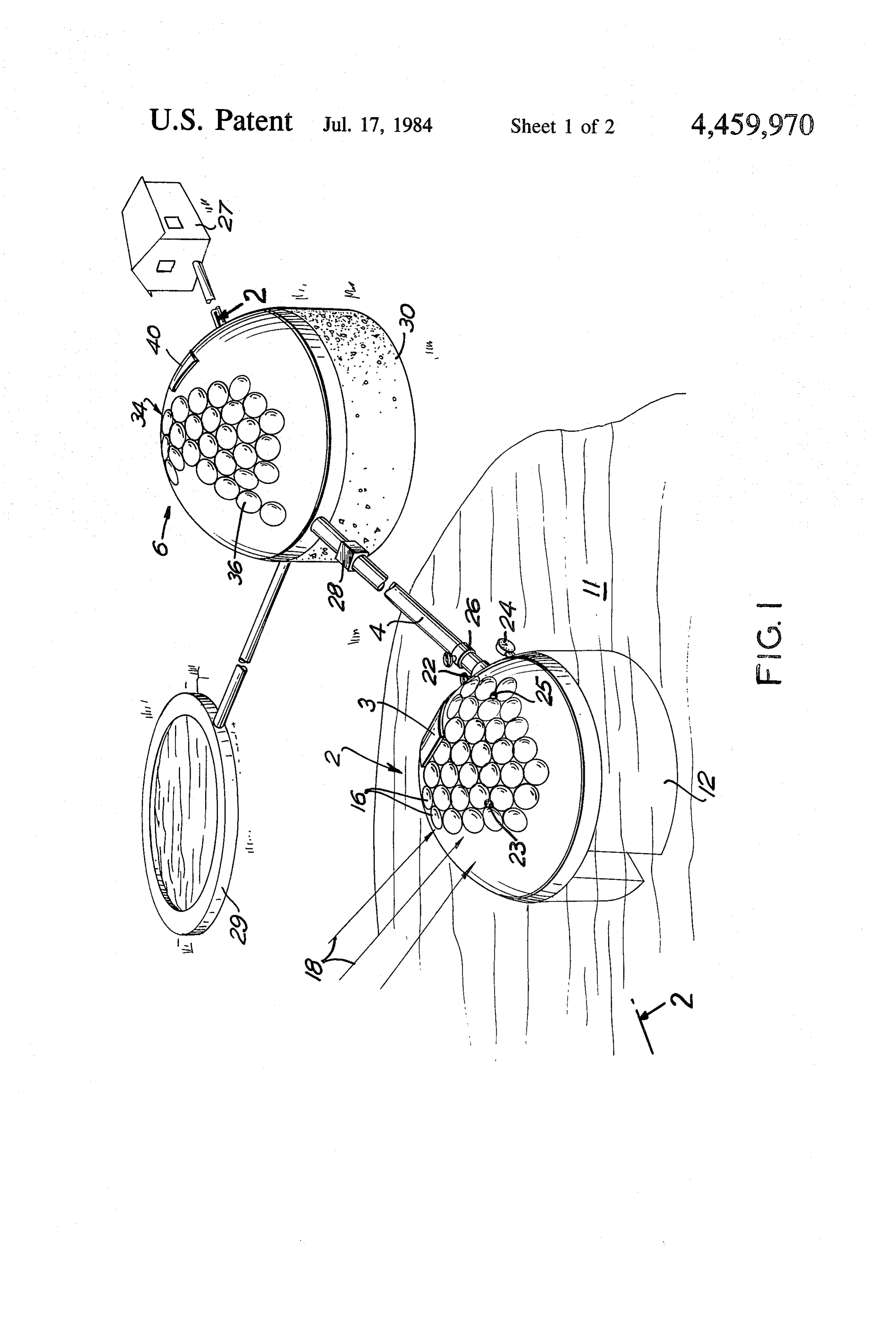
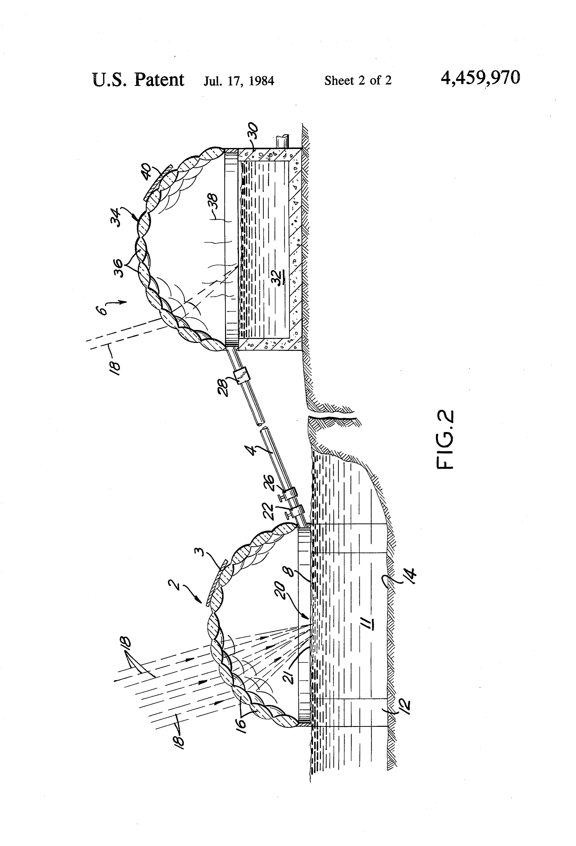
FIG. 1 is a perspective view from above of the solar automatically controlled.
Page 2drawing sheetscan →
Page 3drawing sheetscan →
Page 4scan →
ately heat water which is constantly being replaced by
SOLAR STEAM GENERATING AND cool water.
DISTRIBUTION SYSTEM U.S. Pat. No. 4,166,769 discloses a sphere-like struc ture for concentrating solar energy within a core
BACKGROUND OF THE INVENTION 5 wherein fluid is heated and it may be utilized to gener 1. Field of the Invention ate steam. In this case, however, a whole body of water The present invention is concerned with the utiliza must be heated as opposed to a rapid heating steam tion of solar energy to producesteam and hot water for system which vaporized surface water within a limited use in heating residences, swimming pools, and other O confined area. , , , utilizations for which solargenerating of hot water is SUMMARY OF THE INVENTION presently used.
In addition to providing apparatus for producing The present invention comprises apparatus for gener steam and hot water, the present invention may be uti ating steam utilizing solar energy and includes a distri lized for obtaining fresh potable water from salt water 15 bution system for the solar generated steam to distant or from other water sources which contain various points through a network of intermediate booster sta impurities in solution or suspended form by vaporizing tions which also utilize solar energy. The system also the water to separate it from the unwanted contents. may be utilized as the means for the distribution of The present invention also provides a system for irrigation water.
transferring water from one location to another utilizing The system is especially useful for providing clean solar energy. Since the water is transferred in vaporized 20 water suitable for irrigation and drinking from salt form, it is also possible to transfer the water from one water sources and even from sources of water contami level to a higher level using solar energy. This is partic nated by sewage. The distribution system is also useful ularly advantageous if the system is adapted for use in in delivering clean water to a point at an elevation irrigation systems. higher than the source utilizing solar energy without The development of solar energy is of increasing 25 employing mechanical pumping apparatus or energy importance because of the world-wide shortage of pe sources other than solar.
troleum and other conventional fuel sources, the nega The steam-generating apparatus comprises a green tive environmental effects of using some conventional houselike structure erected over the surface of a body of fuels and nuclear fuels, as well as the increasing eco 30 water which is the source of the water for the system. nomic strains on the nation caused by the rapidly in creasing cost of conventional fuels, especially petro The structure is comprised of at least one and preferably of multiple prisms or lenses arranged in a pattern to leum. Among some of the practical drawbacks of the concentrate available sun rays throughout the day, de greater utilization of solar energy up to now have been pending upon the sun's position, on a confined area of the inability to conveniently generate very hot water or the surface of the water within the structure, at or just steam using solar energy as the source and to distribute below the surface of the water so as to cause rapid the energy generated by solar sources. heating and vaporization of the surface water to gener An object of the present invention is to provide an apparatus utilizing solar energy to generate steam by ate steam. Preferably the lenses should be mounted to concentrating the rays of solar energy on a limited sur change azimuth and elevation angle to track the sun face area on a confined water supply to cause a rapid 40 during the day to maintain the maximum exposure to vaporization of the water in a confined area to produce and concentration of rays at or just below the surface of steam efficiently. The water, which is surface vapor the water. The structure is built to withstand low pres ized, is confined within a greenhouse-type structure sure steam so that "a head of steam' may be developed. made up of multiple prisms or lenses arranged to con Known types of pressure relief valves are incorporated centrate the sun's rays on the limited surface area and 45 as safety measures and pressure gauges to monitor the constructed strong enough to withstand at least a mod steam In pressure are provided.
order to control the system, relief valves are pro erate steam pressure.
The steam generated may be utilized immediately in vided to release steam to the atmosphere when not distributed. The degree of heating may be controlled by the vicinity of the generator apparatus or distributed covering through conduits to booster stations which will keep 50 shutting portions of the lens structure or otherwise the steam in the vaporized form and add sufficient pres out the solar rays.
When sufficient steam has been generated to produce sure to move through conduits to more booster stations. a positive
The booster stations may serve also as resevoirs for be distributed pressure within the structure, the steam may water in the cases where the sun is not visible as a through conduits to structure(s) for heat source of energy at any particular time and the system 55 ing purposes, hot water, or to warm swimming pools and other known uses.
may also serve as an irrigation distribution system.
The heated water in the form of vaporized water or desired Booster stations are provided in the system when it is steam can be distributed to higher elevations since the to distribute the steam over significant dis steam will rise. The apparatus as indicated may also be tances. This is necessary because without additional utilized to purify water through vaporization and is 60 heat input, the vaporized water would condense. particularly adapted to providing potable water from When booster stations are used in the system, they are salt water sources. provided with controllable check valves on the incom 2. Prior Art ing conduit side in order to prevent unwanted back flow No prior art presently known to the Applicant dis of vapor when the booster stations is vaporizing water. closes a system such as disclosed in this application. 65 The booster stations comprise a reservoir structure U.S. Pat. No. 4,057,048 Maine discloses a solar heating which conventionally is a concrete basin which re structure of a dome configuration of lenses which con ceives either liquid water or condensed steam coming in centrate the sun's rays on a volume of water to moder from the main station, and another greenhouse-like 5 structure for concentrating the sun's rays on the surface from the generator 2 but not in the reverse direction. of the water within the reservoir. The booster station(s) 6 includes a concrete reservoir 30 Shutter controls are provided so that the reservoir for retaining a condensed volume of water 32 and a lens does not overheat in the absence of water therein as covering structure 36 for regenerating the steam from well as for controlling the rate and amount of steam the hot water 32 or putting more energy into the steam regenerated in the reservoir utilizing the vaporized or vapor 38 if it has not been condensed. The dome 34 condensed water from the main station. shown is provided with shutter 40 to prevent overheat BRIEF DESCRIPTION OF THE DRAWING ing of the reservoir 6 if there is no water therein or preventing vaporization of the water 32 if there is no need for steam. The shutters 40 may be manually or
FIG. 1 is a perspective view from above of the solar automatically controlled.
steam-generating, apparatus and distribution system It is evident that the system, in addition to providing according to the present invention; and energy for heat in the form of steam and hot water, may FIG. 2 is a vertical section view through the struc utilize the rays of the sun to transport water from the tures illustrated in FIG. 1 along the lines 2-2. 15
Source 11 through a distribution system to irrigate dis
DESCRIPTION OF AN ILLUSTRATIVE tant land and higher elevations by distribution through EMBODIMENT OF THE INVENTION the booster station 6 system.
The apparatus of the invention also serves to purify
Referring to the accompanying drawing, the steam contaminated generating apparatus is shown in general at 2 with the process, providing source water through the vaporization conduits 4 connecting the generating apparatus 2 with obtain potable wateranfrom efficient means, for instance, to booster station(s) 6 in the system. The apparatus 2 is taminated with sewage. saltwater and/or - water con located on the surface 8 of a body of source water 11 in While the invention has been explained by a detailed the embodiment illustrated. In the example shown, the description of certain specific embodiments, it is under water body 11 comprises salt water contaminated with 25 stood that various modifications and substitutions can sewage.
The apparatus 2 is mounted on a foundation structure be made in any of them within the scope of the ap 12 secured to the bottom 14 of the source of water body pended claims which are intended also to include equiv 11. alents of such embodiments.
While shown in annular dome-like form, the structure 30 What is claimed is:
can be in any suitable form provided lenses or prisms 16 1. A system for the generation and distribution of are able to concentrate the incident solar rays indicated steam by solar energy comprising apparatus for the by lines 18 within a confined area 20 on the surface 8 of Solar energy generation of steam comprising an en the water 11. The structure is provided with routine closed structure over the surface of a body of source control systems for adjusting the azimuth and elevation 35 water, said enclosed structure having a plurality of of the lens-bearing surface to concentrate the available transparent lenses, said lenses adapted to receive inci solar rays on the area 20. Such means are shown sche dent solar rays and focus said rays at or just below the matically at 23 and 25 respectively. surface of said source water within a limited area to A shutter system indicated schematically by 3 may be cause surface boiling of said source water to generate utilized to cut off the solar rays wholly or partially from 40 steam within said enclosed structure, and distribution the surface 21 for control purposes. The concentration conduits from said structure to a place remote from said of the rays on the surface 21 serves to rapidly generate structure and booster stations communicating with said steam through the vaporization of the surface heated apparatus through said conduits, said booster stations water. Once a head of steam is built up, the steam may comprising a reservoir for storing condensed water be removed on a continuous basis from the apparatus 2 45 from said apparatus, an enclosure over said reservoir through the conduits 4. A valve 22 utilized to control including at least one transparent lens to focus incident the flow as desired. solar rays at or just below the surface of said condensed The structure 2 is also provided with a conventional water in said reservoir within a limited area to regener pressure gauge 24 to monitor the pressure and a pres ate steam within said station, and outgoing distribution sure relief valve 26 which is both a safety valve and/or 50 conduits to places remote from said booster stations. , vents steam to the atmosphere when not required for 2. A system as claimed in claim 1 wherein said con distribution through conduits 4. Conduits 4 may be duit between said apparatus and said booster station has connected to a residence 27, swimming pool 29, or a checkvalve to prevent water from flowing from said other user of the steam energy in the immeditate vicin booster station back to said apparatus. - ity or to the booster station(s) 6. The steam or con 55 3. A system as claimed in claim 1 wherein said densed water coming from the conduits 4 into the booster station is at a higher elevation than said appara booster station(s) 6 travels through a one-way check tuS.
valve 28 which permits flow to the booster station(s) 6
Provenance
- Collection
- Patents citing this work
- Pages
- 5
- Method
- pdftotext (the PDF's own text layer) + pdftoppm 300dpi page scans
- Patent office record
- patents.google.com →
- Source
- Google Patents citing-documents table
- Assignee
- Douglas Clee
- Published
- 1984-07-17
- Transcribed from
- patentimages.storage.googleapis.com →