

patent · US4509500A
Solar energy collection apparatus
9 April 1985
Text
Page 1bibliographic recordscan →
United States Patent (19)
Mori
54). SOLAR ENERGY COLLECTION
APPARATUS
76 Inventor: Kei Mori, 3-16-3-501, Kaminoge,
Setagaya-ku, Tokyo, Japan
30 Foreign Application Priority Data
Jan. 26, 1982 JP Japan .................................. 57-10680 Int. Cl. ................................................. F24J 3/02 52 U.S. Cl. ....... ... 126/425; 126/440;
3,493,291 2/1970 Webb .............................. 126/440 X 3,934,573 1/1976 Dandini ......... 126/443 X 3,998,204 12/1976 Fuchs et al. ........................ 126/415 4,136,670 1/1979. Davis .................................. 126/440 4,187,832 2/1980 Tregoning ........................... 126/443 4,223,174 9/1980 Moeller ........................... 126/425 X
4,229,941 10/1980 Hope ............................... 26/443 X 4,267,826 5/1981 Hitt ..................................... 126/440 4,299,201 l/1981 Tsubota ............................... 126/440 4,341,203 7/1982 Bloxson .............................. 26/440
FOREIGN PATENT DOCUMENTS
19549 2/1982 Japan ................................... 126/440 Primary Examiner-Margaret A. Focarino
Attorney, Agent, or Firm-Jordan and Hamburg
A solar ray collection apparatus includes a capsule and a solar ray collector housed in the capsule. The solar ray collector is controlled to chase the sun in response to an output of a photodetector which may be located inside or outside the capsule. The capsule comprises a number of interconnected transparent members which are inclined by a specific angle which effects the most efficient collection of the solar energy at any position of the sun. The apparatus is excellent in mechanical strength and resistivity to wind due to unique configu ration of each transparent member.
16 Claims, 7 Drawing Figures
Drawings
Page 2drawing sheetscan →
Page 3drawing sheetscan →
Page 4drawing sheetscan →
Page 5drawing sheetscan →
Page 6scan →
description and illustrated in the accompanying draw
SOLAR ENERGY COLLECTION APPARATUS ings.
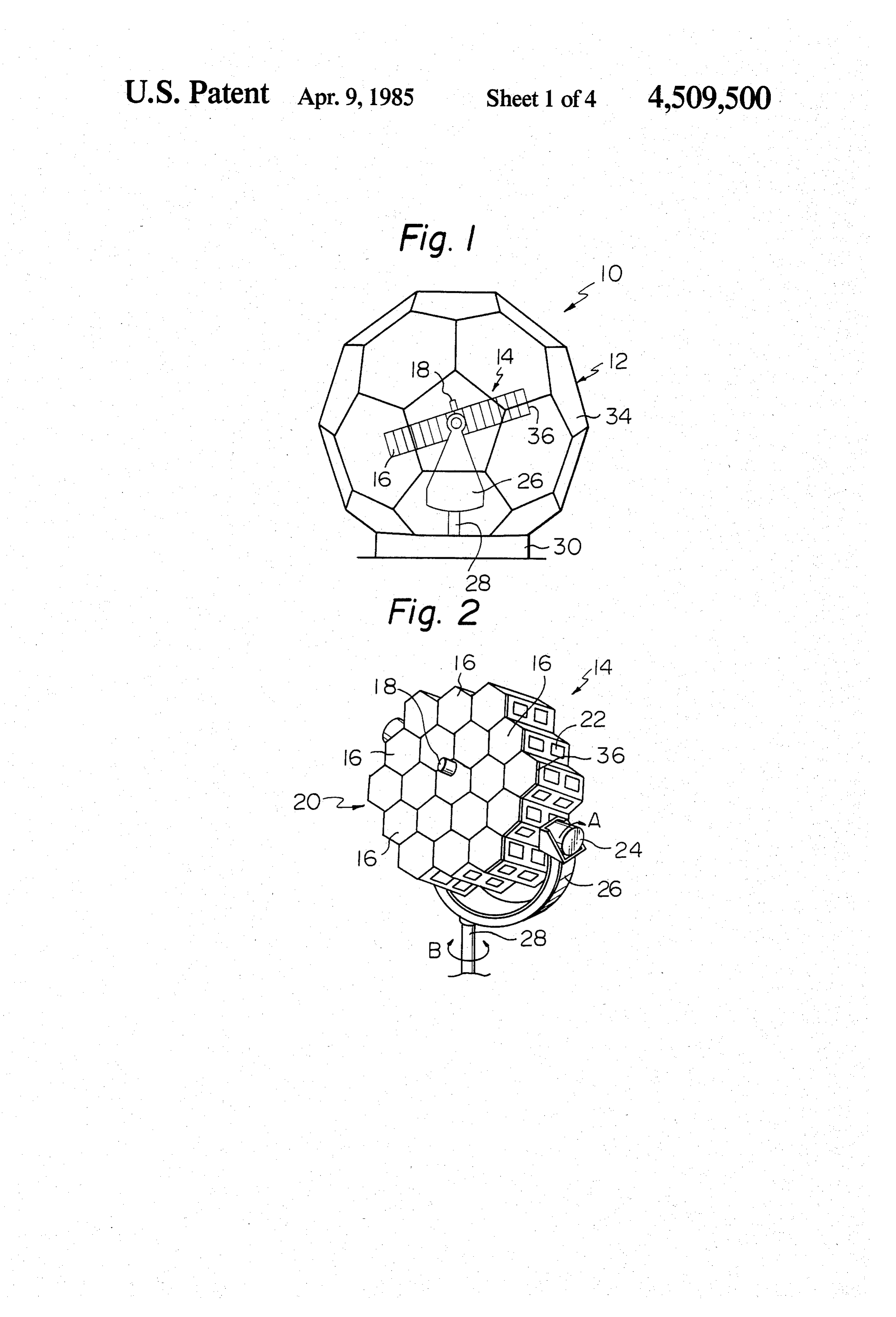
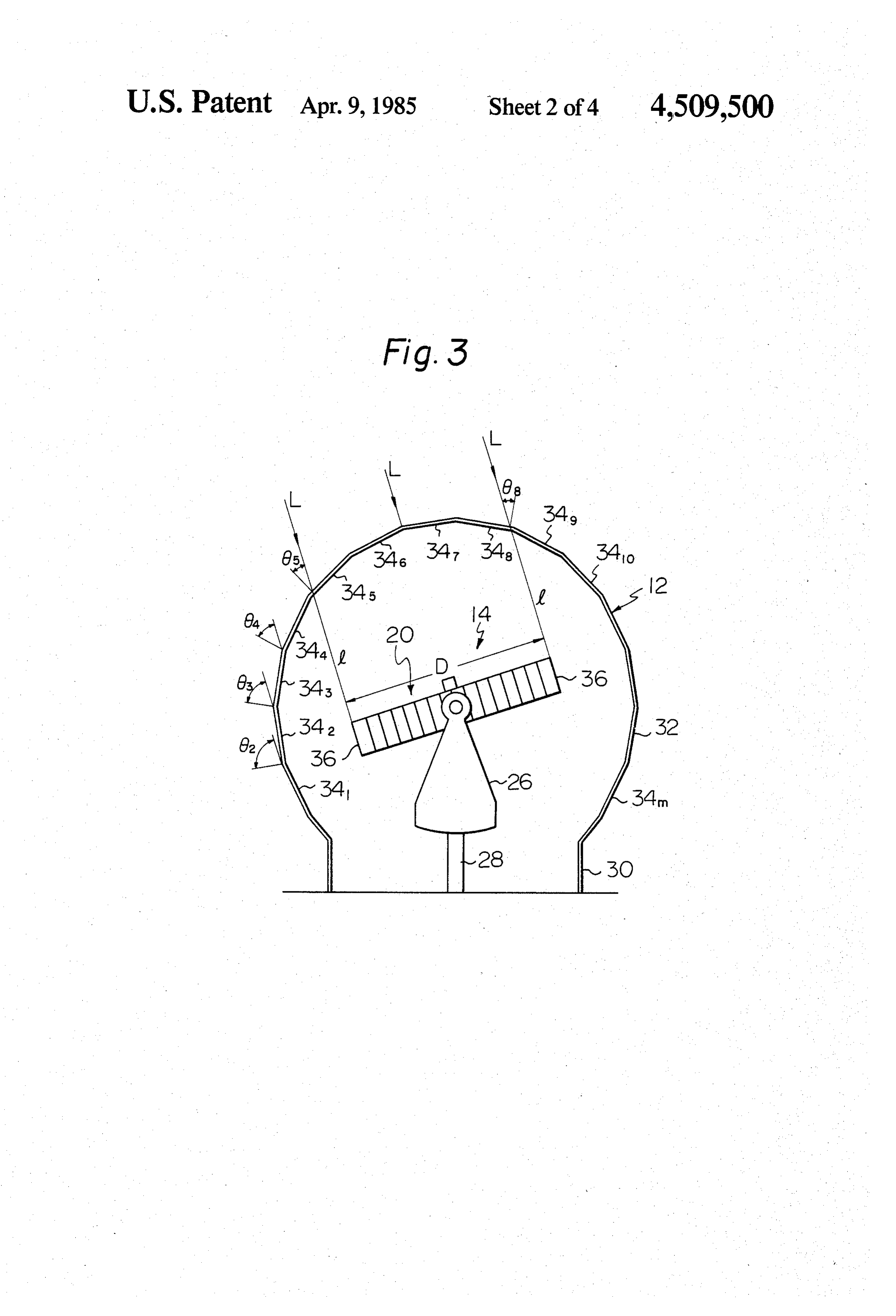
BACKGROUND OF THE INVENTION BRIEF DESCRIPTION OF THE DRAWINGS The present invention relates to an apparatus for FIG. 1 is a schematic front view of a solar energy collecting Solar rays and converting their energy into collection apparatus embodying the present invention; thermal or electric energy and, more particularly, to a FIG. 2 is a perspective view of the apparatus shown Solar energy collection apparatus which includes a in FIG. 1 with its capsule removed;
transparent capsule for protecting its solar ray collector FIG. 3 is a sectional of the apparatus shown in FIG. from wind, rain, dust and other undesirable surround O 1;
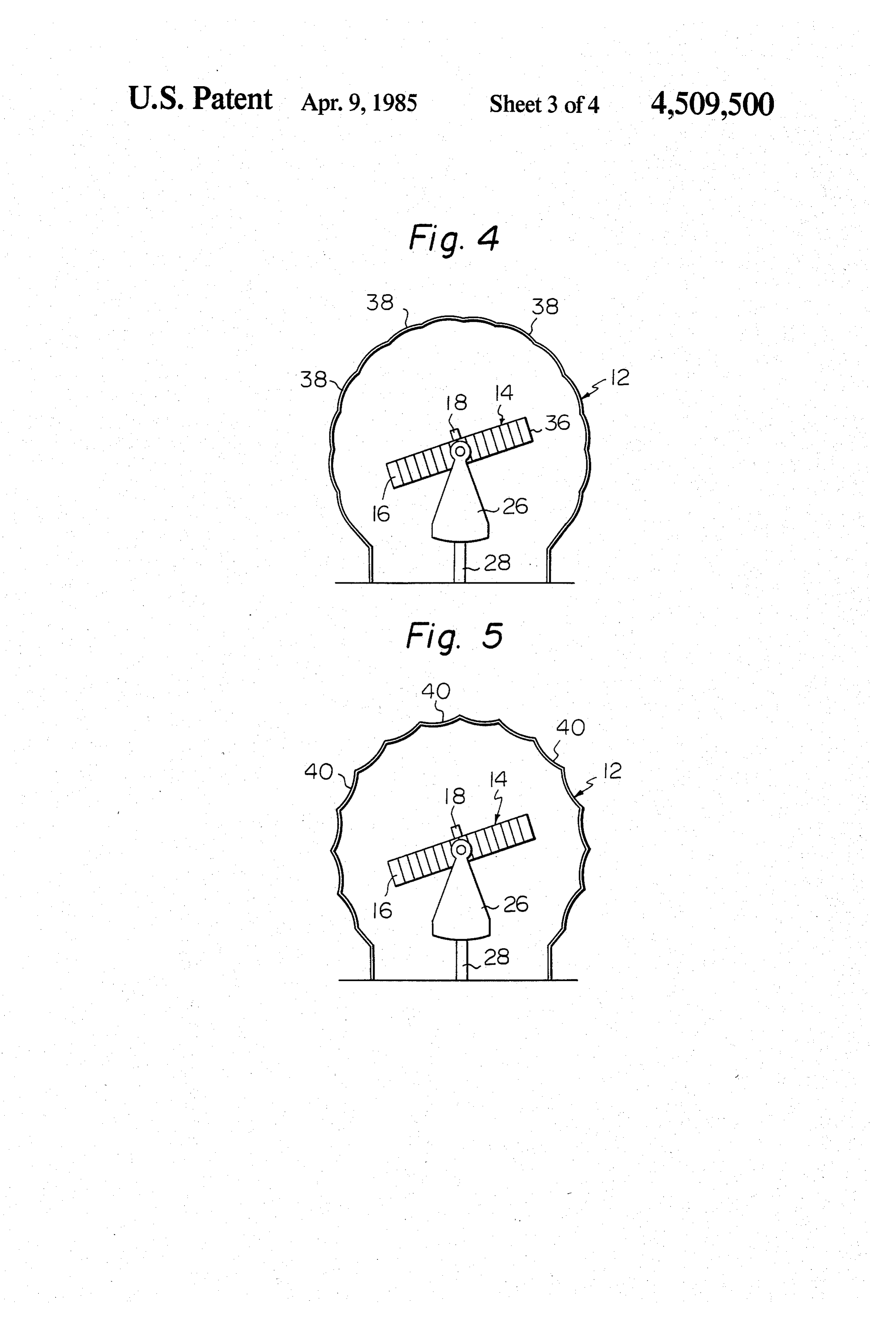
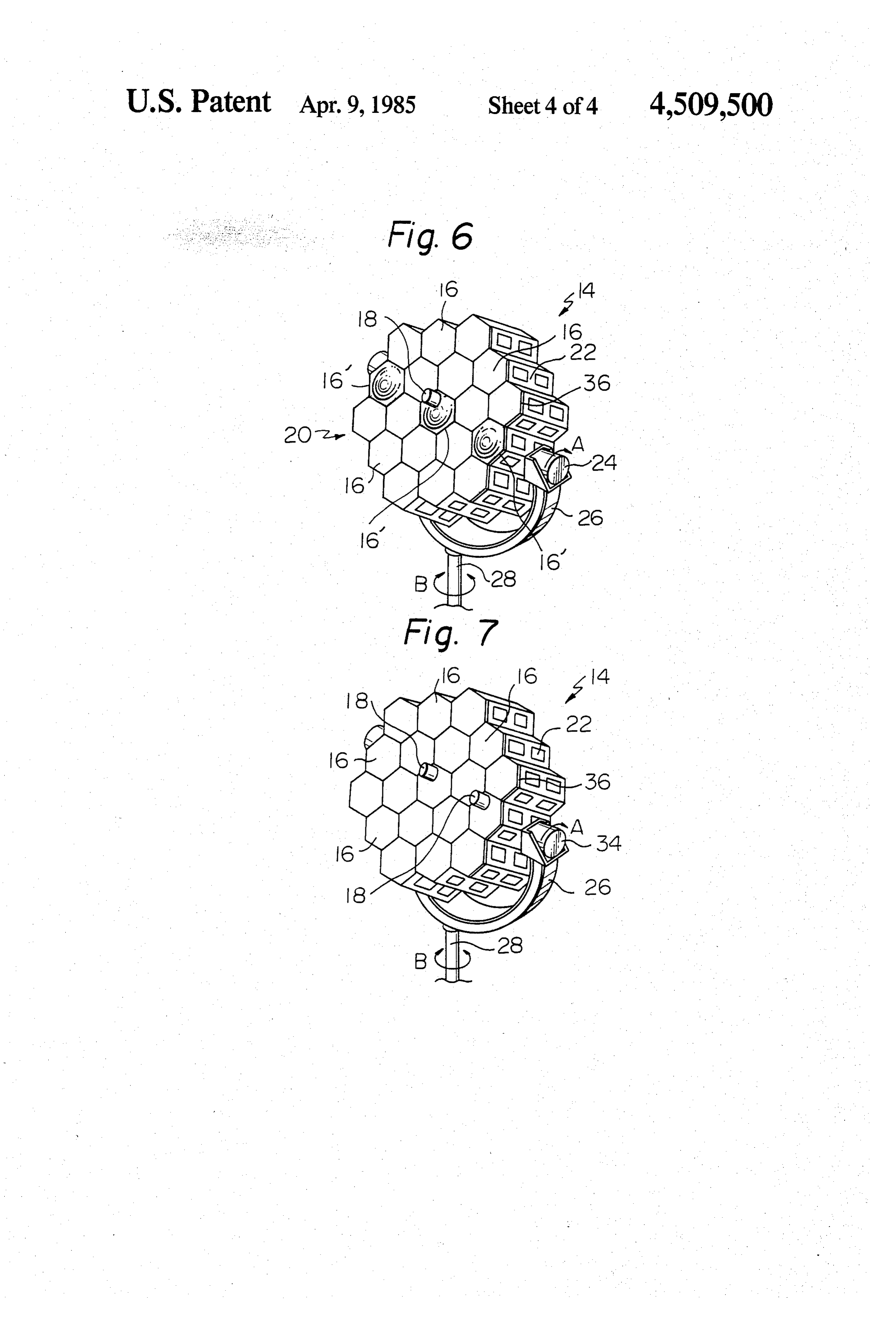
ings. FIGS. 4 and 5 are sections showing other embodi A Solar energy collection apparatus has to be posi ments of the present invention; and tively proofed against various undesirable surroundings FIGS. 6 and 7 are perspective views of other differ such as wind, rain and dust. This demand is usually ent embodiments of the present invention. satisfied by housing a solar ray collector of the appara 15 tus in a generally spherical unitary body or capsule DESCRIPTION OF THE PREFERRED made of transparent material. A problem emerges here EMBODIMENTS is that, when the solar ray collector is bulky, the capsule for accommodating the solar ray collector becomes present invention isenergy
While the solar collection apparatus of the large-sized and it is quite difficult to form such a large 20 embodiments, depending upon of susceptible numerous physical the environment and transparent unitary capsule.
A large-sized capsule may be formed by combining a requirements of use, substantial numbers of the herein number of transparent flat plates at random. This has shown and described embodiments have been made, tested and used, and all have performed in an eminently still suffered from the drawback that the solar ray col satisfactory manner.
lection efficiency achievable with a solar ray collector Referring to FIGS. 1 and 2 of the drawings, a solar housed in such a capsule is quite limited. energy collection apparatus of the present invention is SUMMARY OF THE INVENTION shown and generally designated by the reference nu A solar energy collection apparatus embodying the meral 10. The apparatus 10 comprises a generally spher present invention comprises a housing or capsule made 30 ical transparent housing or capsule 12 and a solar ray up of a number of interconnected transparent members. collector 14 installed in the capsule 12. The solar ray collector 14 includes a number of, such as nineteen,
Solar ray collectors means is installed within the cap lenses 16 adapted to converge the solar rays into photo sule and includes a plurality of lenses. These lenses define a light receiving surface the peripheral edge of thermal or photoelectric converters (not shown) which which contacts imaginary lines which define the range 35 are respectively located at the focal points of the lenses in which the solar rays are allowed to penetrate the 16. A photodetector 18 is positioned at the center of a capsule. With this construction, the solar rays are col generally circular light receiving surface 20 which is lected most effectively for a predetermined size of the defined by the lenses 16. The lenses 16 and photodetec capsule by the solar ray collector means. tor 18 are integrally bundled up by a support frame or In accordance with the present invention, a solar ray 40 lens frame 22. A first drive unit such as a motor 24 collection apparatus includes a capsule and a solar ray drives the lens assembly in a direction indicated by an collector housed in the capsule. The solar ray collector arrow A in FIG. 2. The lens assembly and motor 24 are is controlled to chase the sun in response to an output of integrally supported by a generally C-shaped arm 26 a photodetector which may be located inside or outside which is rigidly mounted on a rotary shaft 28. This shaft the capsule. The capsule comprises a number of inter 45 28 extends perpendicular to the axis of rotation of the connected transparent members which are inclined by a motor 24 and is driven in a direction indicated by an specific angle which effects the most efficient collection arrow B by a second drive unit such as a motor (not of the solar energy at any position of the sun. The appa shown). The photodetector 18 senses a position of the ratus is excellent in mechanical strength and resistivity sun at any time. The first and second motors are con to wind due to unique configuration of each transparent 50 trolled in response to an output of the photodetector 18 member. such that the light receiving surface 20 of the lens as It is an object of the present invention to provide a sembly 16 constantly chases the sun. The solar rays are solar energy collection apparatus which includes an converged by the lenses 16 into their associated photo improved polyhedral capsule to eliminate the drawback thermal or photoelectric converters to be thereby trans discussed above. 55 formed into thermal or electric energy. If desired, opti It is another object of the present invention to pro cal cables may be so located as to receive the converged vide a large-sized solar energy collection apparatus sunlight at the focal points of the respective lenses 16 which is capable of collecting solar rays with the best and transmit it to any desired location for a desired efficiency despite such a size of a polyhedral capsule. application.
It is another object of the present invention to pro 60 As best shown in FIG. 3, the capsule 12 comprises a vide a solar energy collection apparatus having an im generally cylindrical base section 30 and a generally proved capsule which is made up of a plurality of wind spherical or dome-shaped section 32 which emerges resisting and mechanically strong transparent members. from the top of the base section 30. The dome 32 is It is another object of the present invention to pro made up of a plurality of interconnected pentagonal and vide a generally improved solar energy collection appa 65 hexagonal transparent plates 341, 342 . . . 34. The solar ratus. ray collector 14 is controlled to constantly face the sun Other objects, together with the foregoing, are at at the light receiving surface 20 thereof, as previously tained in the embodiments described in the following described. Hence, when the solar rays are incident on 7 the capsule 12 in the direction L as shown in FIG. 3, the Additionally a capsule of the apparatus is resistive to incidence angle 62 on the plate 342, for example, is so wind and excellent in mechanical strength. large that the sunlight is not introduced into the capsule Various modifications will become possible for those 12 but totally reflected by the plate 342. Still, the inci skilled in the art after receiving the teachings of the dence angle 63 on the adjacent plate 342 is smaller than present disclosure without departing from the scope the incidence angle 02 and the incidence angle 04 is even thereof. For example, the entire light receiving surface smaller than the incidence angle 63. Therefore, at a 20 of the lens assembly may be provided with a gener certain incidence angle smaller than 62, the sunlight is ally hemispherical configuration. The photodetector 18 allowed to penetrate the capsule 12. It follows that the may be replaced by a sun chasing unit located outside installation of the solar ray collector 14 will be most 10 the capsule 12 and constructed to drive the solar ray effective when its diameter D is so designed as to locate collector 14 with its output.
the peripheral edge 36 of the light receiving surface 20 What is claimed is:
at the position which the light of the specific incidence 1. A solar ray collection apparatus comprising: angle smaller than 62 reaches. Stated another way, the 15 solar ray collector means for collecting the solar rays, most effective design of the capsule 12 will be such that said means including a plurality of lenses which supposing lines l which extend from the peripheral edge define a light receiving surface; and 36 perpendicularly to the light receiving surface 20, the a housing or capsule made up of a number of inter plates 345 and 348 intersecting the lines l are inclined by connected transparent members plates which are angles 65 and 68 which have the maximum value within interconnected to enclose the solar ray collector the allowable range for the penetration of the solar rays means thereinside, said transparent plates being into the capsule 12. inclined at a plurality of different angles and being With the above arrangement, the solar ray collector configured such that, when intersected by imagi 14 inside the capsule 12 can collect the solar rays or nary lines which extend from the peripheral edge energy in its most effective manner. of the light receiving surface, perpendicularly to Referring to FIG. 4, another embodiment of the pres 25 the light receiving surface, the transparent plates ent invention is shown which is essentially similar to the are inclined relative to said imaginary lines by the first embodiment but different in the profile of the trans maximum value within the angular range which parent plates of the capsule 12. In contrast to the flat allows the sun rays to penetrate the capsule. 2. An apparatus as claimed in claim 1, further com profile of the plates 34, the plates 38 shown in FIG. 4 30 prising are individually formed slightly convex toward the tion of at least one photodetector for sensing the posi the sun.
outside. It will be seen that such a shape of the transpar ent plates 38 increases the mechanical strength of the of3.theAntransparent apparatus as claimed in claim 2, in which each capsule 12 and, therefore, permits the plates 38 to be toward the outside.plates of the capsule is formed convex formed thinner than the plates 34. Alternatively, the 35 capsule 12 may be made up of transparent plates shown of4.theAntransparentapparatus as claimed in claim 2, in which each plates of the capsule is formed con in FIG. 5 which are individually formed somewhat cave toward the outside.
concave toward the outside. The capsule shown in 5. An apparatus as claimed in claim 4, in which the FIG. 5 will prove particularly resistant to wind. transparent plates comprise the combination of pentag Apart from the described combination of pentagon 40 and hexagon, the transparent plates may have any other onal and hexagonal transparent plates. 6. An apparatus as claimed in claim 5, in which the
Suitable configuration in principle, such as triangle, light receiving surface of the solar ray collector means circle, quadrangle, pentagon, hexagon, trapezoid and is formed flat.
banana-shaped or a combination thereof. Still, the com 7. An apparatus as claimed in claim 1, in which the bined pentagonal and hexagonal plates can be effec 45 Solar ray collector means has an axis for rotation about tively interconnected without any gap to enhance the which the light receiving surface is rotatable, specific resistivity of the resulting capsule 12 to wind. ones of the lenses which intersect said axis having a Referring to FIG. 6, another embodiment of the pres profile which resembles the profile of a convex lens. ent invention is shown which is similar to the construc 8. An apparatus as claimed in claim 5, in which the tion shown in FIG. 2 but features a unique lens arrange light receiving surface of the solar ray collector has a ment. Of the lenses 16 shown in FIG. 6, the lenses 16 generally partial spherical configuration. intersecting the axis of rotation of the motor 24 have a 9. An apparatus as claimed in claim 2, in which the profile which resembles a convex lens. With this ar. photodetector is located outside the capsule. rangement, the focal point of each lens 16' is prevented 10. An apparatus as claimed in claim 2, in which the from intersecting the axis of rotation of the motor 24. 55 photodetector is positioned inside the capsule. Referring to FIG. 7, still another embodiment of the 11. A Solar ray collection apparatus comprising: present invention is shown which includes a plurality of Solar ray collector means for collecting the solar rays, photodetectors 18. While the single photodetector 18 in Said means including a plurality of lenses which the foregoing embodiments will fail to properly operate define a light receiving surface; and when the joint between adjacent transparent plates of 60 a housing or capsule made up of a number of inter the capsule 12 becomes located just thereabove, either connected transparent plates which are intercon one of the photosensors 18 shown in FIG. 7 will always nected to enclose the solar ray collector means and accurately sense the sun even when the other fails thereinside, said transparent plates comprising the in the situation mentioned above. combination of pentagonal and hexagonal transpar In summary, it will be seen that the present invention 65 ent plates, said transparent plates being inclined at provides a large-sized solar energy collection apparatus a plurality of different angles and being configured which efficiently collects the solar energy despite the Such that, when intersected by imaginary lines use of a capsule which is formed by numerous plates. which extend from the peripheral edge of the light 8 receiving surface perpendicularly to the light re trating said housing substantially at said maximum inci ceiving surface, the transparent plates are inclined dent angle.
relative to said imaginary lines by the maximum 14. An apparatus as claimed in claim 12, wherein said value within the angular range which allows the housing has a general configuration representing a por Sun rays to penetrate the capsule. 5 tion of a sphere.
12. A solar energy collection apparatus comprising: 15. A solar energy collection apparatus comprising: a housing made up of a number of interconnected a housing made up of a number of interconnected transparent plates, said transparent plates being transparent plates, said transparent plates being inclined at a plurality of different angles such that disposed at a plurality of different angles such that when the solar rays are incident on the housing, the 10 when the solar rays are incident on the housing, the incident angle on each of said transparent plates incident angle on each of said transparent plates also varies, said housing being constructed and also varies, said housing being constructed and arranged such that at least some of said transparent arranged such that at least some of said transparent plates have incident angles less than a maximum plates have incident angles less than a maximum angle of which solar rays are allowed to penetrate 15 angle of which solar rays are allowed to penetrate the housing, others of said transparent plates have the housing, others of said transparent plates have incident angles exceeding said maximum angle at an incident angle exceeding said maximum angle at which solar rays do not penetrate the housing, and which solar rays do not penetrate the housing, and solar ray collector means for collecting solar rays, solar rays collector means for collecting the solar said means being installed within the housing and 20 rays, said means being installed within the housing including a plurality of lenses, said lenses defining a and including a plurality of lenses, said lenses defin light receiving surface having a peripheral edge, ing a light receiving surface having a peripheral said light receiving surface being constructed and edge, said light receiving surface being constructed arranged such that said solar rays penetrating said and arranged such that said solar rays penetrating housing intersect said light receiving surface, said 25 said housing intersect said light receiving surface, light receiving surface being further constructed said light receiving surface being further con and arranged such that said peripheral edge is lo- structed and arranged such that said peripheral cated at a position defined substantially by the light edge is located at a position defined substantially by of said maximum incident angle which penetrates the light of said maximum incident angle which said housing along imaginary lines which extend 30 penetrates said housing along imaginary lines from the peripheral edge of said light receiving which extend from the peripheral edge of said light surface perpendicularly to said light receiving sur- receiving surface perpendicularly to said light re face; ceiving surface;
whereby the solar ray collector means collects the whereby the solar ray collector means collects the solar rays most effectively for a predetermined size 35 solar rays most effectively for a predetermined size of the capsule. of the capsule.
13. An apparatus as claimed in claim 12 in which said 16. An apparatus as claimed in claim 15, wherein said light receiving surface is generally flat, said peripheral transparent plates comprise interconnected pentagonal surface being defined by a circle, said circle being de- and hexagonal transparent plates. fined by imaginary lines representing solar rays pene- 40 sk sk : k sk
Provenance
- Collection
- Patents citing this work
- Pages
- 8
- Method
- pdftotext (the PDF's own text layer) + pdftoppm 300dpi page scans
- Patent office record
- patents.google.com →
- Source
- Google Patents citing-documents table
- Assignee
- Kei Mori
- Published
- 1985-04-09
- Transcribed from
- patentimages.storage.googleapis.com →