

patent · US4509502A
Multiple lens cover for solar heating panel
9 April 1985
Text
Page 1bibliographic recordscan →
United States Patent (19)
Youcha
54 MULTIPLE LENS COVER FOR SOLAR
HEATING PANEL
Inventor: Jack Youcha, 100 Elm Dr.,
Levittown, N.Y. 11756
Int. Cl. ................................................. F24J 3/02 52 U.S. C. ............... ............ 126/440; 126/449
3,986,491 10/1976 O’Hanlon ........................ 126/440 X 4,057,048 11/1977 Maine .................................. 126/440 4,077,393 3/1978 Mattson ..... ... 126/440 X 4,098,263 7/1978 Lanciault ............................ 126/440 4,136,670 1/1979 Davis ......... ... 126/440 4,188,941 2/1980 Hopkins. ... 126/440 4,299,201 11/1981 Tsubota ..... ... 126/440 4,341,201 7/1982 Ziemann ............................. 126/440
4,341,204 7/1982 Boxson .............................. 126/440
FOREIGN PATENT DOCUMENTS
34058 4/1981 Japan ................................... 126/440 46947 4/1981 Japan ................................... 126/440 146954 ll/1981 Japan ................................... 126/440 151844 11/1981 Japan ................................... 26/44 Primary Examiner-Margaret A. Focarino
Attorney, Agent, or Firm-Nolte, Nolte and Hunter
A transparent cover for a solar panel has a number of uniform undulations or ridges across its surface. The cover is formed of a plurality of lens elements arranged over the entire surface of the cover and at specifican gles along the ridges. The lenses focus and intensify the incident solar radiation onto the thermal collector ele ments of the panel.
1 Claim, 4 Drawing Figures
Drawings
Page 2drawing sheetscan →
Page 3drawing sheetscan →
Page 4drawing sheetscan →
Page 5drawing sheetscan →
Page 6scan →
Multiple lens cover for solar heating
The manner in which this and other objects are ac complished by the present invention will be set forth in
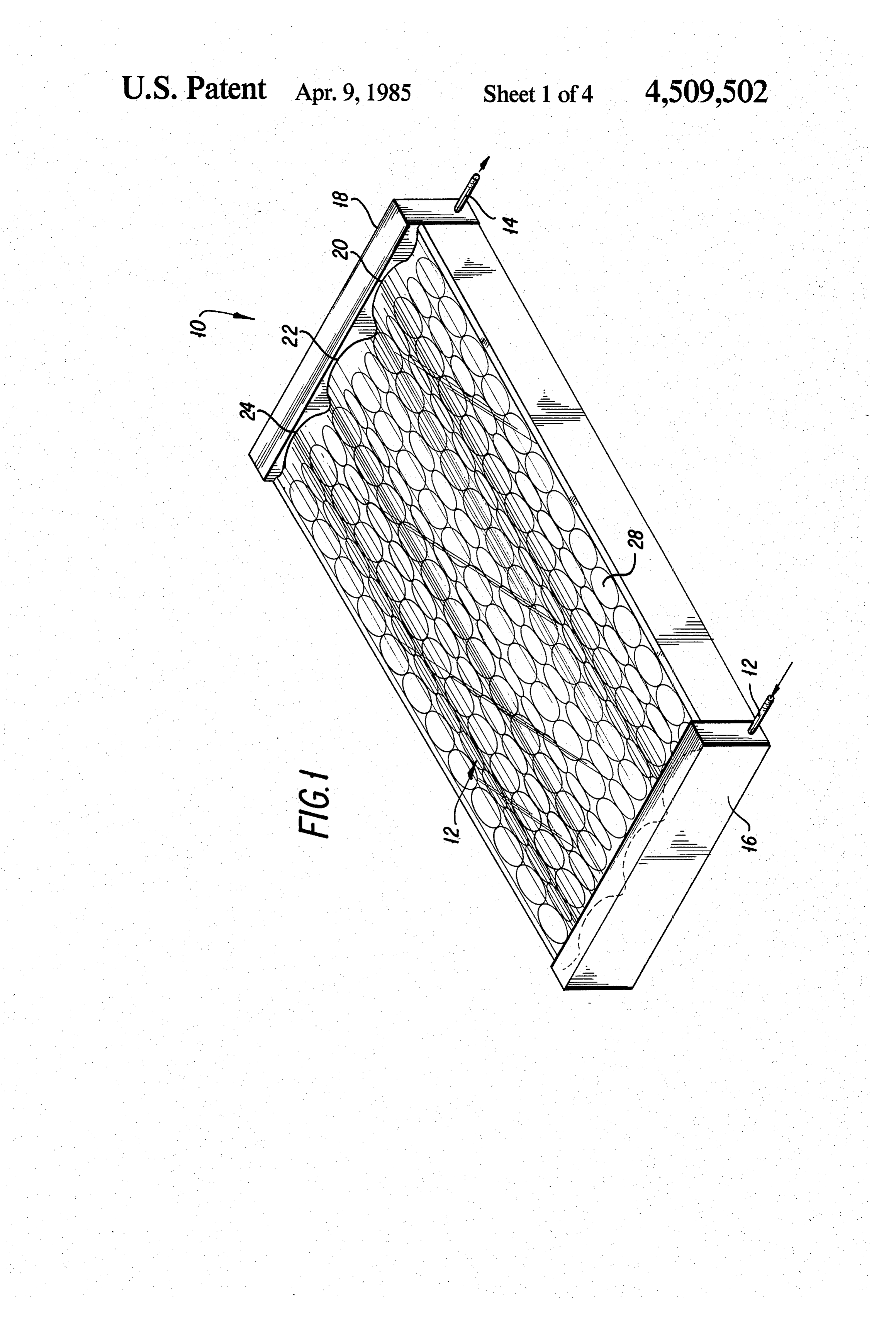
PANEL the following detailed description of the invention. BACKGROUND OF THE INVENTION 5 BRIEF DESCRIPTION OF THE DRAWINGS The present invention relates in general to a transpar FIG. 1 is a perspective of the inventive multiple lens ent cover for a solar heating panel and, specifically, solar panel cover;
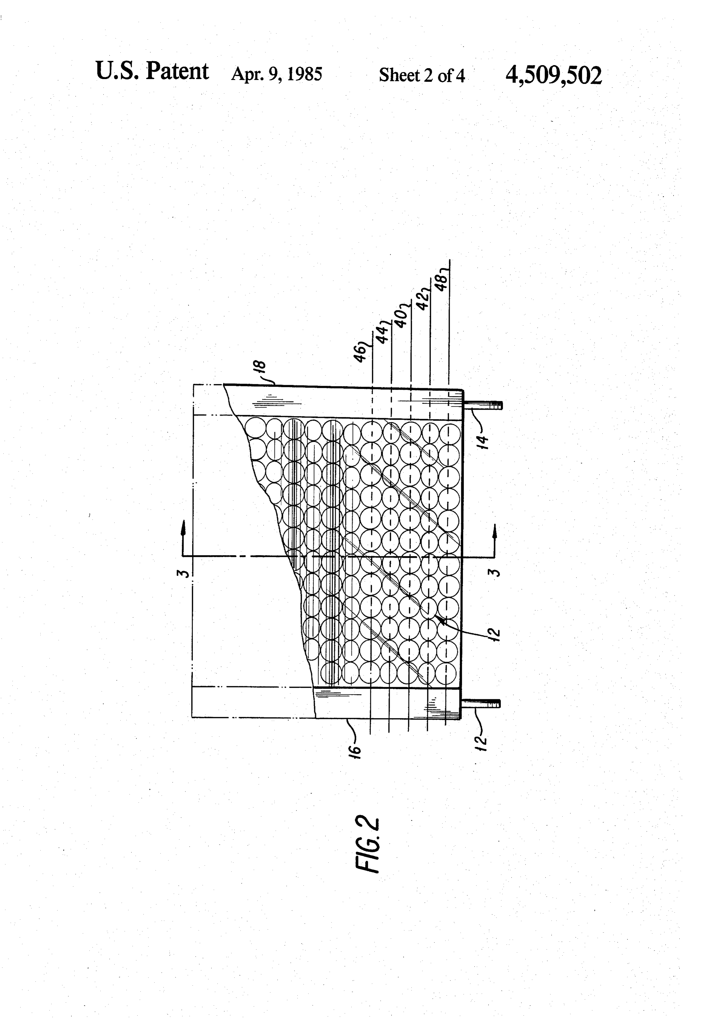
relates to a transparent cover sheet integrally formed lensFIG. 2 is a top plan view of the inventive multiple with a plurality of lenses that serve to focus, magnify, 10 FIG. 3 panel solar cover;
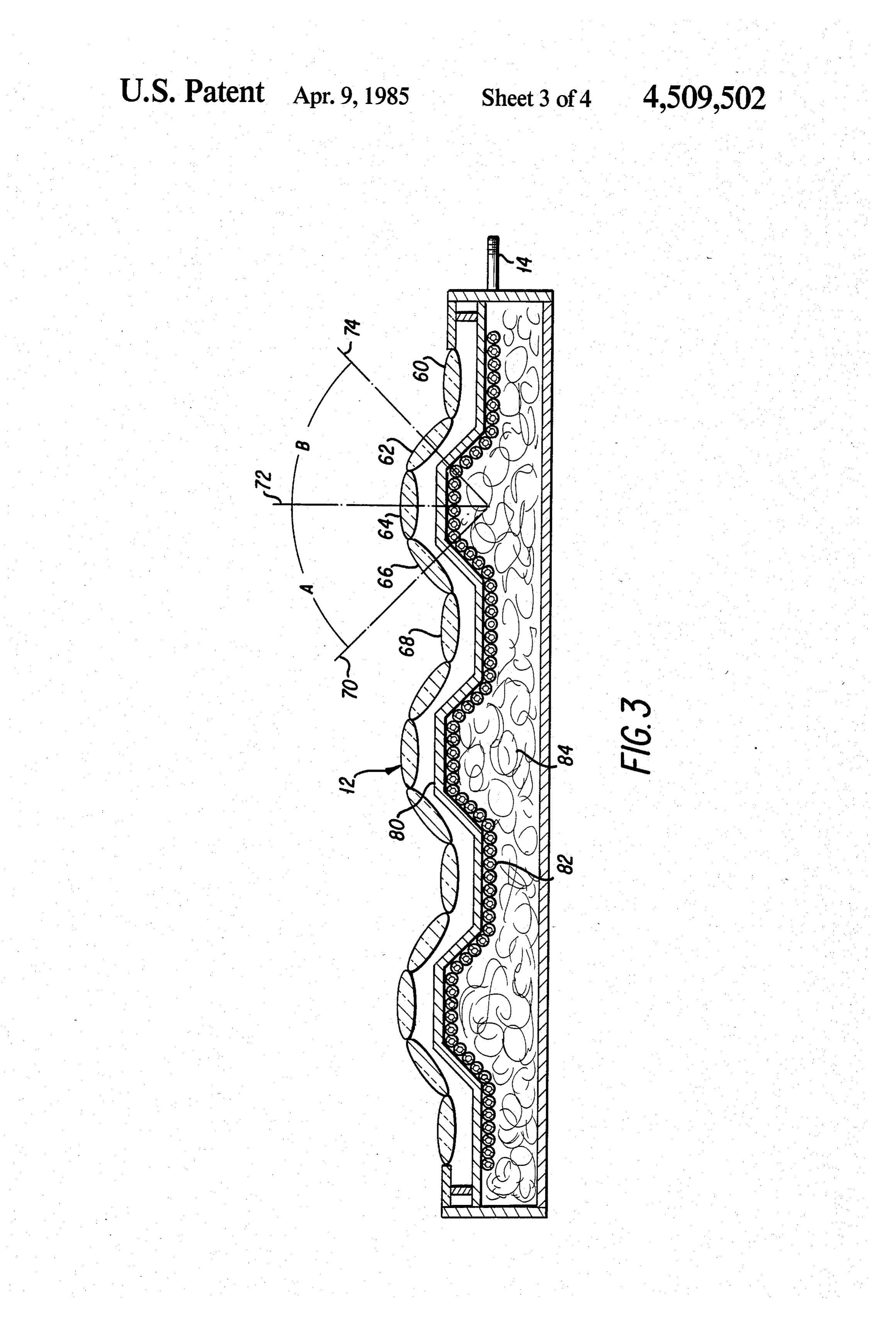
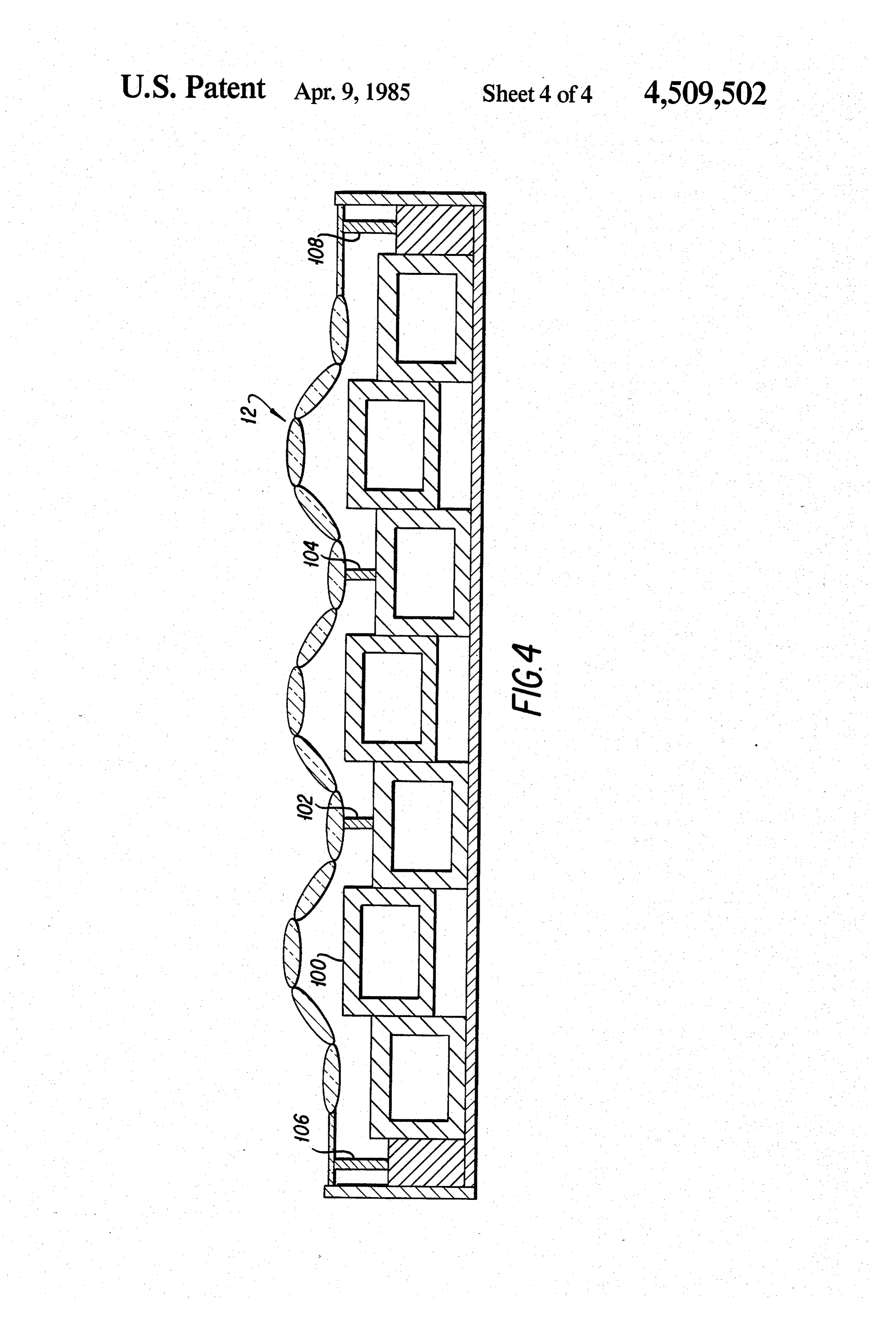
is a side elevational view in cross section, and intensify the solar radiation onto the heat absorbing taken along section lines 3-3 in FIG. 2; and elements of the panel. FIG. 4 is a side elevational view in cross section, The use of solar panels to heat fluids by solar radia showing the present invention in use with an alternate tion has become exceedingly popular and the attendant kind of heat collecting assembly.
technology has become more and more refined. The 15 solar panels typically employ thermal collectors formed DETAILED DESCRIPTION OF THE of metal plates and tubes or extrusions upon which the INVENTION solar radiation falls and through which the fluid to be Referring now to FIG. 1, a typical solar panel 10 is heated passes. These collectors are sealed from the shown having the inventive multiple lens cover 12 in weather by transparent covers formed of a plate-like 20 stalled thereon. This kind of solar heat collector usually glazing, such as conventional glass window panes, has a plurality of fluid containing tubes, not seen in FIG. Plexiglas, or the like. The principal purpose is to pro 1, which are connected to appropriate fluid inlet and vide a transparent surface that protects the collector outlet conduits, 12 and 14, respectively, by headers or tubes from the elements, yet permits the solar radiation manifolds 16, 18. The fluid tubes may be covered by, to pass through and fall on the heat collecting elements 25 and thermally connected to, metal plates. The inventive inside the solar panel. multiple lens cover has a number of periodic ridges, The typical solar panel is preferably installed with a undulations, or waves, and in this embodiment three Southern exposure at a predetermined angle and then such ridges are shown at 20, 22, 24 in FIG. 1. Arranged fixed to the roof. This is an attempt to maximize the on each of these three ridges are three rows of individ amount of solar radiation received by the panel, how 30 ual lens elements, with an additional row arranged in ever, in order truly to maximize the solar radiation the transitional "valley' between adjacent ridges. Each falling on the panel the best approach is to mount the lens element is identical, with one such lens being indi solar panel on some pivotable means, so that the panel cated typically at 28. The lens elements 28 focus and can track the sun through its apparent traverse of the intensify all solar radiation incident thereon, and partic sky. Needless to say, such solar panel tracking systems 35 ularly at three particular locations in the sun's apparent are so expensive, cumbersome, and overly complex as traverse of the sky on the internally arranged collector to be prohibitive to the homeowner. elements that absorb the heat from the sun. The lens elements should be collecting or positive
SUMMARY OF THE INVENTION lenses, typified by any of the common lenses, such as The present invention provides an undulated trans biconvex, plano-convex, or positive meniscus. parent cover for a solar heating panel that is formed Referring now to FIG. 2, the specific arrangement of having a plurality of integral lens elements arranged at the individual lens elements in the rippled or undulated specific angles on the surfaces of the ridges. The lens cover may be seen more clearly, since FIG. 2 is a top elements serve to focus and intensify the solar radiation plan view of the assembly of FIG. 1. The alignment and falling on the internally arranged heat collecting ele 45 number of lenses, which make up each undulation or ments of the panel. The inventive lens cover is not a flat ripple in the plate assembly, is shown specifically. The dashed line 40 represents the alignment of the centers of planar sheet but, rather, has a rippled or undulated those lenses arranged at the top of one of the ridges. surface with the lenses being arranged in longitudinal This line of lenses serves to focus the solar radiation at rows on this rippled surface parallel to the undulations. 50 midday, i.e.,
In this way, a fixed proportion of the total number of This assumes when the sun is substantially overhead. that the solar panel is flat on the ground, lenses will be directly facing the sun, as it apparently however, traverses the sky during the day. That is, the solar rays slanted within respect practice since the solar panel will be to the ground so that the midday will always be aligned with the axis of at least some of position corresponds to the time when the sun lies on a the collecting lenses forming the inventive lens cover. 55 line drawn perpendicular to the overall surface of the The multiple lens cover can be installed as original panel. At such time, the vertical rays would be aligned equipment on new solar panels or can be retrofit to with the axes of those lenses arranged along dashed line existing panels by removing the existing transparent 40.
cover and installing the inventive cover. Because the line 42 are arranged along one side or wall with The lenses whose centers are aligned dashed the ridge multiple lens cover intensifies the solar radiation on the 60 and have their central axes at substantially a 45° angle, collecting elements, each solar panel produces more with respect to the axes of the lenses arranged along line available thermal energy so that fewer panels are re 40. Similarly, those lenses whose centers are arranged quired per installation. along dashed line 44 are on the opposite side of the ridge Accordingly, it is an object of the present invention from the lenses on line 42 and also are arranged with to provide a transparent cover for a solar heat panel that 65 their axes at a 45° angle with respect to the vertical, or focuses and intensifies the solar radiation incident upon the axes of the top lenses arranged along dashed line 40. the panel, so as to improve the efficiency of the heat The angle subtended by the axes of the two angularly collecting elements of the panel. arranged lenses, shown generally at 42 and 44 is 90.
Page 7scan →
The transition zones between the successive raised single piece or as long strips fastened together, or the ridges also have a plurality of lenses arranged therein. cover may be similarly formed of molded plastic. The Dashed line 46 represents a row of these transition zone present invention also contemplates forming the indi lenses. The axes of these lenses are parallel to the axes of vidual lens elements of glass and imbedding them in a the lenses arranged along the top of the ridges, as shown 5 transparent plastic matrix. In any event, the cover by dashed line 40. Similarly, transition areas are located should be formed so that each lens contacts all adjacent on the outside edges of the cover 12 and lenses are again lenses, in order to maximize the lens surfaces available placed in these zones and arranged with their axes par and to minimize the amount of interconnecting or ma allel to the axes of the uppermost lenses along line 40, as trix material required.
well as with the transition zone lenses along line 46. One O FIG. 4 shows the use of the inventive multiple lens such outer row is represented by dashed line 48. This solar panel cover being used with a solar panel, having arrangement then proceeds for as many periodic repeti a different kind of collector assembly specifically, one tions as required to cover the surface of the solar panel. formed of a number of box-like extrusions, typically FIG. 3 is a side elevational view, in cross section, made from aluminum. In other words, instead of the taken along section lines 3-3 of FIG. 2 and shows the 15 angled-surface plate 80 and the plurality of pipes 82, as arrangement of the individual lens elements as they shown in the embodiment of FIG. 3, the solar heat form the undulations in the sheet. Specifically, one of collector employs a number of elongate, box-like extru the lenses forming the outer transition zone 48 in FIG. sions, shown typically at 100. The present invention 2 is shown in cross section at 60, one of the lenses in the also operates advantageously with this kind of solar slanted or side row, such as row 44 in FIG. 2, is shown 20 in cross section at 62. One of the lenses in the uppermost collector cover and, as may be seen, the undulations of the follow generally the outline of the collector as row, as shown at 40 in FIG. 2, is seen in cross section at sembly. In this embodiment, supports 102 and 104 are 64, and the other slanted row lens, on line 42 in FIG. 2, employed and these supports, in conjunction with the is seen in cross section at 66. The transition lens on line 46 of FIG. 2 is seen in cross section at 68. 25 end supports 104, 108, determine the spacing between The specific angular arrangement between the axes of the inventive cover 12 and the collector elements 100. the three different angularly arranged lenses is shown in 104, 106 andthe108height
By varying the of these supports or spacers 102, desired temperature may be ob
FIG. 3. Specifically, the angle between axis 70 of lens 66 and axis 72 of lens 64 is represented as A, and in the tained at the heat collector surface. It should be noted present embodiment this angle equals approximately that the present invention provides a quite efficient 45. Similarly, the angle between axis 74 of lens 62 and focusing and intensifying of the radiation onto the col axis 72 of lens 64 is represented as Band, in this embodi lector elements and, thus, it is possible that the collector ment, also equals 45. The total subtended then being elements may overheat. In order to preclude this, and to 90. control the heat produced, the length of elements 102, The embodiment of FIG. 3 employs a ridged metal 35 104, 106, and 108 are chosen specifically. This spacing plate 80 as an element of the collector for the solar applies to the embodiment of FIG. 3 as well. radiation. This plate 80 is preferably formed of alumi It is understood that the foregoing is presented by num, or other metal having a high thermal conductiv way of example only and is not intended to limit the ity, with a matte black finish and is arranged in intimate scope of the present invention, except as set forth in the contact with a plurality of fluid conduit tubes shown 40 appended I claim:
claims
typically at 82. The water or other fluid is heated as it passes through these tubes 82 and the solar radiation 1. A cover for use with a solar panel, comprising a that has been focused and intensified by the inventive sheet of transparent material having periodic undula multiple lens cover onto the various flat surfaces of the tions forming parallel elongate upraised ridges, each heat absorbing plate 80 is transferred through plate 80 45 said ridge having a top and sides and a valley extending to tubes 82 to heat the fluid. The water or other fluid in between adjacent ridges in the surface thereof, and a tubes 82 flows in the appropriate direction, i.e., either in plurality of solar heat collecting lens means integrally or out of the conduits 12 and 14, as determined by other formed in said sheet and being arranged substantially apparatus in the solar heating system. In this embodi over the entire surface of said sheet, said lens means ment some form of insulation 84 is arranged inside the 50 being arranged substantially in longitudinal rows Solar panel around the tubes 82 to prevent the heat aligned with said ridges, whereby said lens means focus absorbed by the tubes from being lost. and intensify incident solar radiation onto heat collect The multiple lens cover 12 of the present invention is ing elements of the solar panel, said solar heat collecting formed of lenses that are clear or transparent to solar lens means being arranged in three rows along each of radiation, as is the matrix in which the lenses are ar 55 said elongate upraised ridges, one of said rows of lens ranged, but they are substantially opaque to long wave means being arranged on the top of said ridge, and a length radiation that might be produced by the metal row of lens means being arranged along each side of collector assembly. The solar radiation that provides said elongate upraised ridge, each lens means being the heat is essentially made up of shorter wavelengths formed as a substantially circular lens substantially con passes through the lens plate and impinges on the col 60 tiguous to its next adjacent circular lenses, each lens lector surface, yet the heat radiated from the collector having a central axes, and wherein said lenses arranged surface would be longer wavelength radiation that will along the sides of said upraised ridges are arranged at not pass easily back through the lens plate 12. angles such that the angle subtended by the central axes The cover in the present invention containing the of said two side rowsck iss 90.k multiple lenses may be formed of molded glass as a 65 k
Provenance
- Collection
- Patents citing this work
- Pages
- 7
- Method
- pdftotext (the PDF's own text layer) + pdftoppm 300dpi page scans
- Patent office record
- patents.google.com →
- Source
- Google Patents citing-documents table
- Assignee
- Jack Youcha
- Published
- 1985-04-09
- Transcribed from
- patentimages.storage.googleapis.com →