

patent · US4511755A
Solar ray collection apparatus
16 April 1985
Text
Page 1bibliographic recordscan →
United States Patent (19)
Mori
(54) SOLAR RAY COLLECTION APPARATUS
Inventor: Kei Mori, 3-16-3-501, Kaminoge,
Setagaya-ku, Tokyo, Japan
30 Foreign Application Priority Data
May 17, 1982 JP Japan .................................. 57-8477 Jun. 3, 1982 JP Japan .................................. 57-95,969 Dec. 31, 1982 JP Japan ................................ 57-23O792
52 U.S. C. .................................... 136/246; 136/259;
4,026,267 5/1977 Coleman ............................. 126/436 4,186,033 /1980 Boling et al.. ... 36/247 4,297,000 10/1981 Fries ............. ... 350/96.24 4,307,936 12/1981 Ochiai ... 350/96.24 4,389,085 6/1983 Mori ................................. 350/96.10
4,411,490 10/1983 Daniel .............................. 350/96.10 Primary Examiner-Aaron Weisstuch
Attorney, Agent, or Firm-Jordan and Hamburg
A Solar ray collection apparatus includes a plurality of lenses mounted on at least one of the opposing flat sur faces of a lens mount. A plurality of light conducting members equal in number to the lenses are carried by a conductor mount which is held integral with and spaced from the lens mount by spacers and a frame, so that the focal point of each lens may coincide with the . nearby end of its associated light conductor. The lenses, lens mount, conductor mount, spacers, and frame are made of materials the coefficient of expansion of which is equal to or substantially equal to each other, thereby overcoming the influence of the solar heat. Positioning means may be employed which moves the end of each light conducting member into alignment with the center of the adjacent lens, and then to the focal point of the lens and then fixes it in position. Stray beams in the apparatus may be converted into electrical energy at a suitable position or positions in the apparatus.
24 Claims, 11 Drawing Figures
Drawings
Page 2drawing sheetscan →
Page 3drawing sheetscan →
Page 4drawing sheetscan →
Page 5drawing sheetscan →
Page 6drawing sheetscan →
Page 7scan →
accurately positioning a light conducting member rela
SOLAR RAY COLLECTION APPARATUS tive to a lens, so that the focal point of the lens may register with a light input end of the conductor.
BACKGROUND OF THE INVENTION It is another object of the present invention to pro The present invention relates to a solar ray collection vide a generally improved solar ray collection appara apparatus for converging solar rays or energy and rout tuS.
ing it through a light conducting member to a desired A solar ray collection apparatus embodying the pres remote station for illumination or like purpose. ent invention includes a plurality of lenses and a first A solar ray collecting and transmitting apparatus, transparent flat support member for supporting the which I have proposed, uses Fresnel lenses to converge O lenses on at least one of opposite surfaces thereof. A solar rays and fiber optic cables to transmit the con plurality of light conducting members equal in number verged light to a remote station for illumination and to the lenses are supported by a second transparent flat other applications. Such an apparatus, winning increas support member. The second support member is inte ing appraisal today, requires a system which is capable grally connected to the first support member in a prede of provision with a relatively large capacity and pro 15 termined spaced and parallel position. The light con duction on a quantity basis in contrast to the conven ducting members are carried by the second support tional nonquantity production of small capacity appara member in such positions that one end of each of the tuses. Therefore, while the apparatus has to be of a light conducting members faces one of the lenses associ structure which is suitable for a larger capacity and a ated therewith and coincides with a focal point of the mass-production line, merely modifying the prior art 20 one lens.
apparatus to increase its scale would not only render the The above and other objects, features and advantages structure intricate but would result in considerable time of the present invention will become apparent from the and labor necessary for focusing lenses in the course of following description taken with the accompanying assembly. drawings.
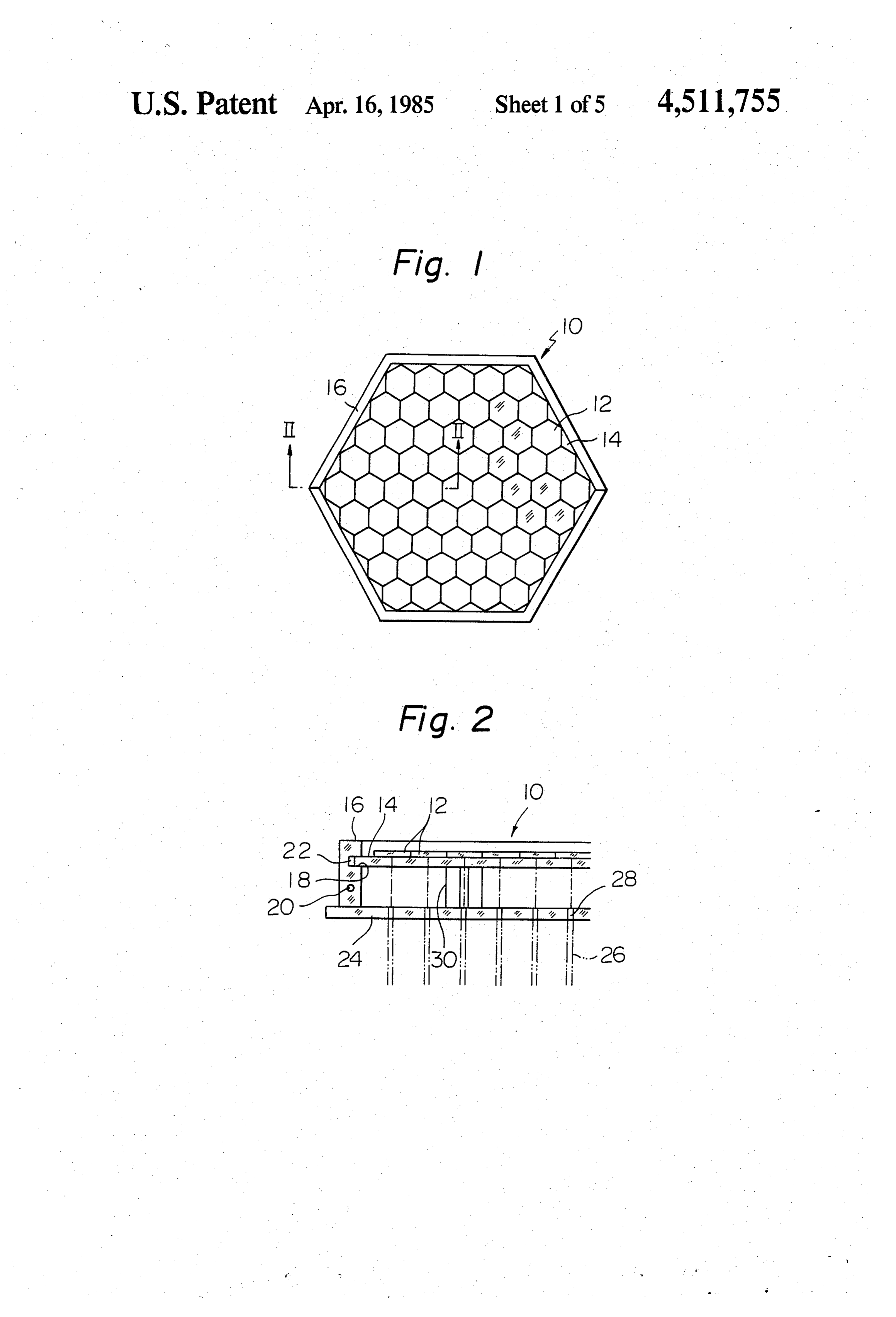
In detail, the prior art solar ray collector includes two 25 or more tubular members each having a hexagonal BRIEF DESCRIPTION OF THE DRAWINGS cross-section and combined with the others to consti tute a framework. Hexagonal Fresnel lenses are at tusFIG. 1 is a front view of a solar ray collection appara embodying the present invention;
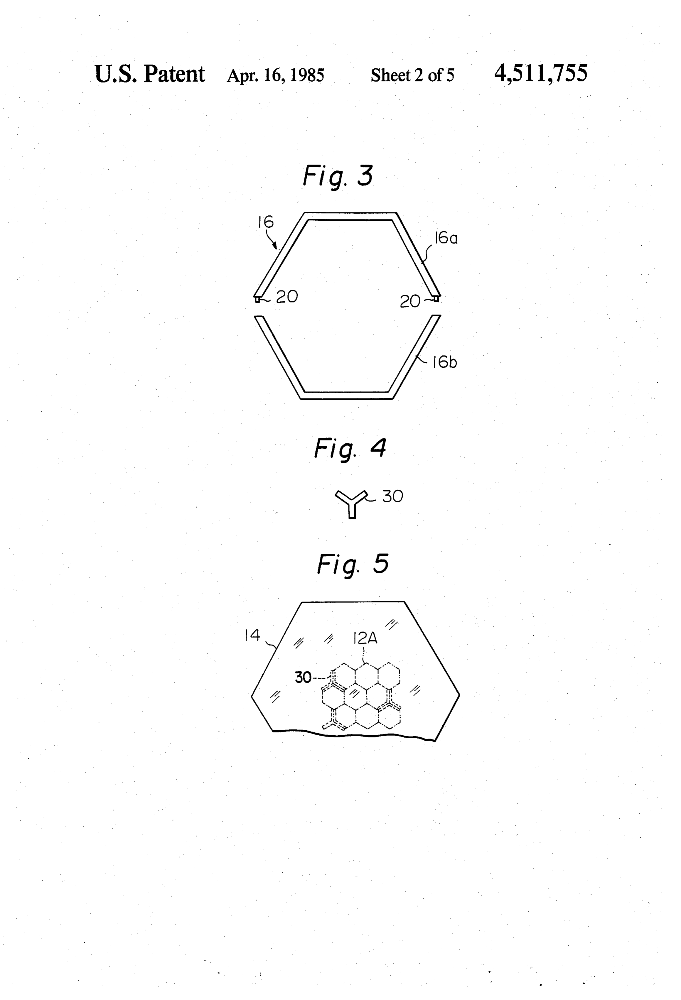
tached one by one to the ends of the individual tubular FIG. 2 is a section along line II-II of FIG. 1; members. Due to such a number of Fresnel lenses, an 30 attempt to increase the capacity of this type of appara in FIG. 3 is an exploded plan view of a frame included the apparatus of FIG. 1;
tus would invite significant intricacy in the operation for focusing the lenses. Also, the resulting number of theFIG. 4 is a plan view of a spacer which forms part of construction shown in FIG. 2;
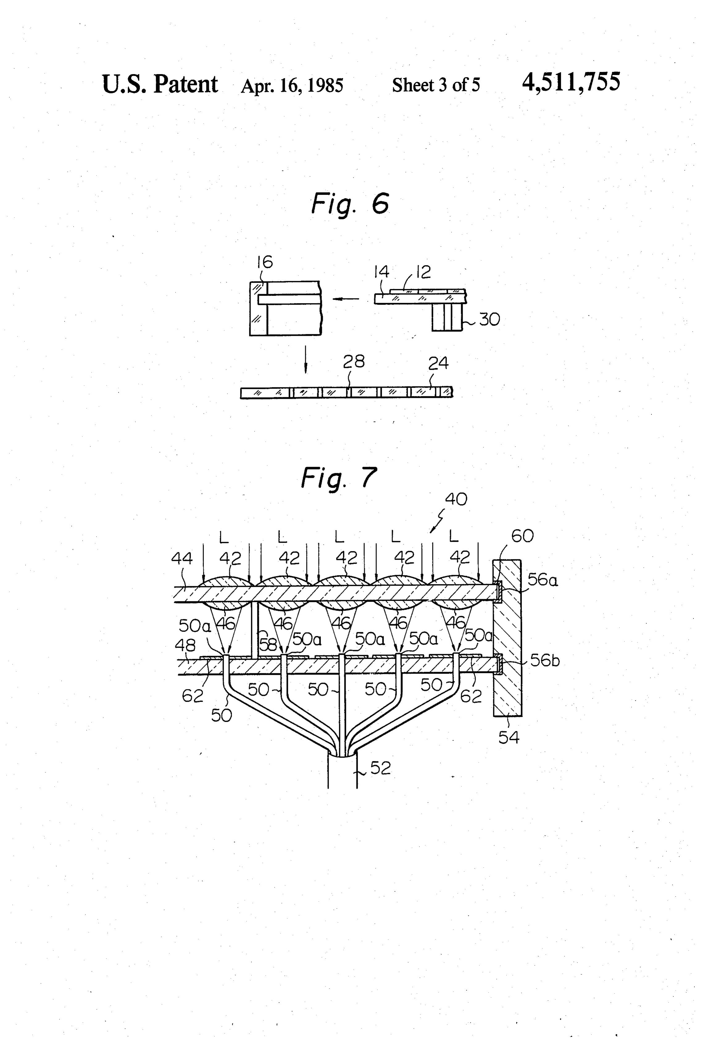
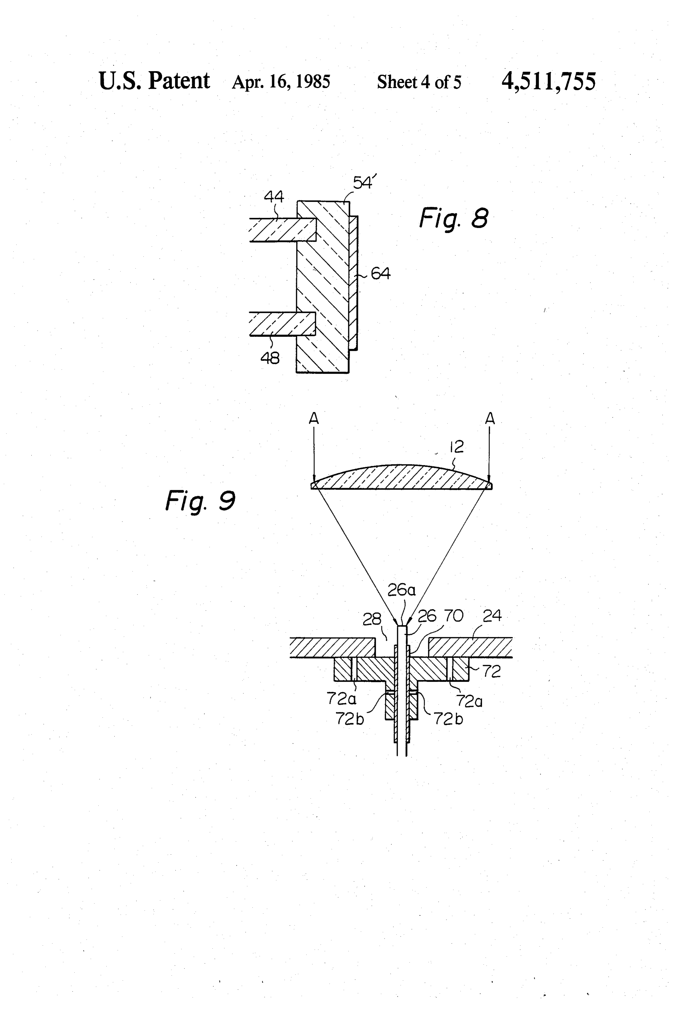
lens support elements would make the overall structure complicated and heavy and, thereby, the time and cost 35 FIG. 5 is a view of the spacers and lenses shown in an required for production would be prohibitive. exemplary position relative to each other; In light of the above, a large size lens may be desired rayFIG. 6 is a fragmentary exploded view of the solar collector demonstrating a procedure for assembling for assembling a solar ray collector having a large ca pacity. This, however, suffers from the drawback that it; v-, the lens has to be designed each time to a specific capac 40 FIG. 7 is a view similar to FIG. 2 but showing an ity of a solar ray collector at the sacrifice of the cost. It other embodiment of the present invention; is also known that large size lenses bring about various FIG. 8 is a fragmentary view of a modification to the problems when coupled with fiber optic cables. construction shown in FIG. 7; Meanwhile, a solar ray collector is inevitably effected FIG. 9 is a section of a device for positioning a light by the solar heat due to the construction and operation 45 conducting member relative to a lens in accordance particular thereto. The solar heat tends to expand struc with the present invention;
tural elements of the apparatus to different extents and, FIG. 10 is a shematic diagram representing an assem thereby, totally destruct the required optical features bly of solar ray collectors of the present invention thereof, e.g. focal points of the lenses. which may be employed for a larger collection capac 50 ity; and
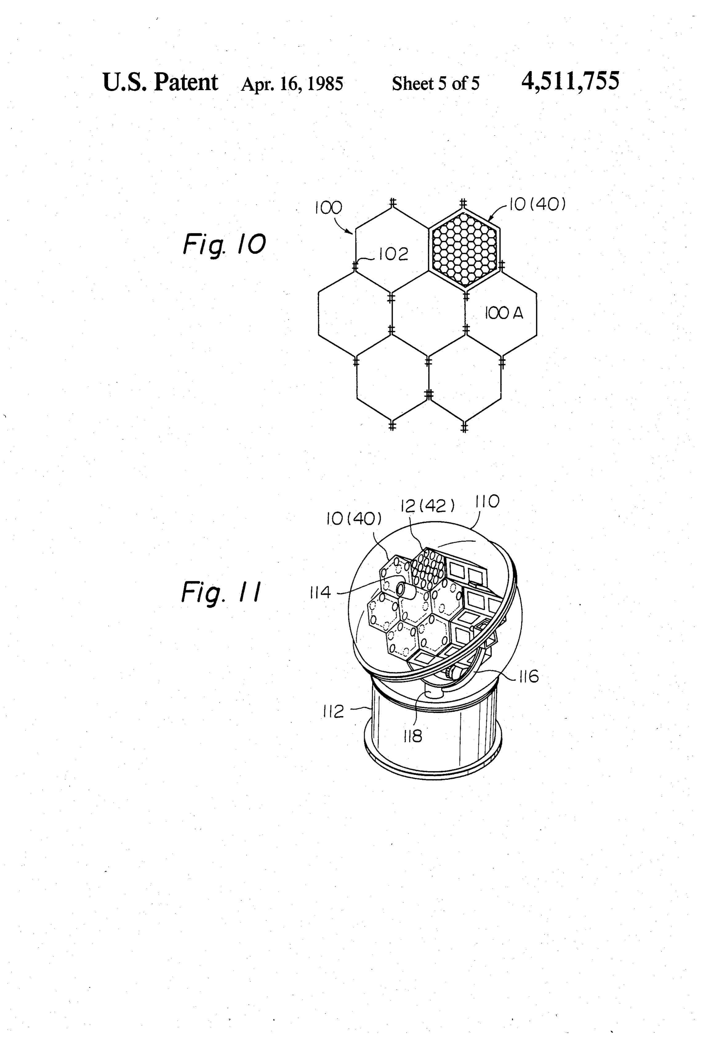
SUMMARY OF THE INVENTION FIG. 11 is a perspective view of the assembly of FIG. It is therefore an object of the present invention to 10 which is in practical operation encapsulated in a provide a solar ray collection apparatus which is suit housing.
able for large capacity design and quantity basis produc DESCRIPTION OF THE PREFERRED tion. 55
It is another object of the present invention to pro EMBODIMENTS vide a solar ray collection apparatus which is produc While the solar ray collection apparatus of the pres ible at a low cost regardless of its capacity. ent invention is susceptible of numerous physical em It is another object of the present invention to pro bodiments, depending upon the environment and re vide a solar ray collection apparatus which achieves a 60 quirements of use, substantial numbers of the herein light collection efficiency incomparable to the prior art shown and described embodiments have been made, apparatus of the type described. tested and used, and all have performed in an eminently It is another object of the present invention to pro satisfactory manner.
vide a solar ray collection apparatus which is furnished Referring to FIG. 1 of the drawings, a solar ray col with an adequate countermeasure against the effects of 65 lection apparatus embodying the present invention is solar heat. shown and generally designated by the reference nu it is another object of the present invention to provide meral 10. The collector 10 comprises a mass of hexago a solar ray collection apparatus which is capable of nal lenses 12 which are rigidly mounted on a flat hexag 8 onal lens mount 14 and arranged in contact with each 30 to the conductor mount 24. Such a procedure is other in a honeycomb structure. The lens mount 14 is illustrated in FIG. 6.
made of a transparent material substantially common to The solar ray collector 10 features various advan the lenses 12, e.g., glass or acrylic composition, and tages as will be described. Any desired number of the elastically retained by a hexagonal frame 16 as will be collectors 10 can be assembled together to a required described hereinafter. capacity, using the same structural elements. This, cou Referring also to FIG. 2, the lens mount 14 carrying pled with the small size of each lens 12, accomplishes the lenses 12 thereon is received along peripheral edges economical production of such solar ray collector. The thereof in a groove or recess 18 which is formed in the light conductors 26 can be accurately positioned rela inner periphery of the frame 16. As best shown in FIG. 10 tive to the lenses 12 merely by uniting the lens mount 14 3, the frame 16 comprises frame halves 16a and 16b and conductor mount 24 with each other via the spacers which are shaped to form a hexagon when mated to 30. The absence of any special positioning mechanism gether. Pins 20 are studded on opposite ends of the will simplify the construction and reduce the weight. frame half 16a, while holes (not shown) for receiving Because the lenses 12, lens mount 14, frame 16, conduc the pins 20 are formed in both ends of the counterpart 15 tor mount 24 and spacers 30 are made of materials 16b. The frame halves 16a and 16b are individually whose coefficients of expansion are substantially the recessed at their inner surfaces so that the groove 18 extends throughout the inner periphery of the hexago same, thermal expansion of the assembly due to the solar heat will not entail distortion or deformation in nal frame 16. A filler 22 made of rubber or like soft elastic material is fit in the groove 18 to yieldably back 20 any part of the assembly or affect the focal point of the lens system.
up the lens mount 14. The filler 22 will compensate for In FIG. 5, the spacers 30 may be positioned symmet or absorb any horizontal expansion of the lens mount 14 rically with respect to a central one of the lenses 12. or vibration applied thereto. The frame 16, like the lens Then, deformation, mount 14, is preferably substantially identical in mate the like would beif any, due to thermal expansion or substantially evenly distributed rial or coefficient of expansion with the lenses 12. 25 throughout the assembly thereby maintaining the lens
As shown in FIG. 2, a second flat mount 24 is posi mount 4 and conductor mount 24 and thereby the focal tioned below and parallel to the lens mount 14. Elon gate light conducting members 26 are individually rig point of each lens and the light input end of the associ idly fit in aperture 28 which are formed through the ated pigtail 26 under a constant relationship. This will conductor mount 24. The location of each light con 30 further enhance the light collection efficiency despite ducting member 26 is such that light incident on a lens any deformation.
12 positioned just thereabove becomes focused on its entReferring invention to FIG. 7, another embodiment of the pres is shown. The collector 40 includes a top, that is, each light conducting member 26 is located at the focal point of its associated lens 12. The light number of first lenses 42 arranged on a transparent lens mount 44. Second lenses 46 smaller than the first 42 are conducting members 26 constitute so-called pigtails, 35 carried on the underside of the lens mount 44 in one-to each of which comprises a crystal rod, quartz fiber, or like single optical element and may be bundled up into one correspondence with the first lenses 42 to form lens a second light conducting member which, although not pairs 42, 46. The optical axes of the lenses 42 and 46 in shown, may be a cable, fiber or tube made of quartz or each pair are aligned with each other. Thus, each lens plastics. With this construction, light incident on each 40 pair 42, 46 constitutes means for converging solar rays lens 12 will be converged into the associated light con L incident thereon. A flat transparent conductor mount ductor 26 through the lens mount 14 and then transmit 48 carries therewith light conducting members or pig ted by the second conductor to a desired location. tails 50 each of which has a light input end 50a facing a The conductor mount 24 is securely connected to the lens pair 42, 46 located just thereabove and being posi lens mount 14 through a plurality of upright spacers 30, 45 tioned at the focal point of the lens 46. With this con which are mounted on the conductor mount 24 and struction, the light L incident in each lens 42 will be have a common generally Y-shaped cross section (see converged thereby into the associated lens 46 held by FIG. 4). The upright spacers 30 will maintain the lens lens mount 44 and, therefrom, into the end 50a of the mount 14 and conductor mount 24 and, thereby, the associated pigtail 50. The reference numeral 52 shows lenses 12 and conductors 26 at a predetermined spacing 50 an example of the second light conducting member from each other. The spacers 30 will also serve the discussed with reference to FIG. 2 and which may function of a reference for positioning the lenses 12 on comprise a fiber optic cable or tube or an optical fiber. the lens mount 14 as will be described later. Again, the The light conducted by the individual conductors 50 spacers 30 are made of a material substantially equal in will be collectively routed by the second light conduc coefficient of expansion to the lenses 12. 55 tor 52 to a desired location. In assembly, the lenses 12 are first arranged in seg The lens mount 44 and conductor mount 48 are inte ments each consisting of several lenses as shown in FIG. grally retained by a frame 54 at a spacing from each 5 by way of example. The spacers 30 are adhered to other which sets up the discussed optical relationship selected positions on the underside of the lens mount 14. between the lenses 46 and the ends 50a of their associ Each lens segment, 12A in FIG. 5, is positioned on the 60 ated pigtails 50. Elastic fillers 56a and 56b intervene lens mount 14 as specified by the spacers 30 and then between the frame 54 and the lens mount 44 and be adhered to the lens mount 14. This creates an integral tween the frame 54 and the conductor mount 48, respec assembly of the lenses 12, lens mount 14 and spacers 30. tively, each for the purpose described in conjunction Thereafter, the peripheral edges of the lens mount 14 with the filler 22 of the first embodiment. are inserted into the groove 18 in the frame 16 and 65 The lenses 42 and 46, lens mount 44 and conductor elastically retained therein by the filler 22. This is fol mount 48 are made of materials whose coefficients of lowed by placing the frame 16 on the conductor mount expansion are substantially the same, e.g. glass or 24 and adhering the other (or lower ends) of the spacers acrylic composition.
Page 9scan →
Spacers 58 are interposed between the lens mount 44 ductor mount 24. Thereafter, the sleeve 70 and thereby and the conductor mount 48. The spacers 58 will not the conductor 26 is moved through the holder 72 along only assist the frame 54 in spacing the mounts 44 and 48 the optical axis of the lens 12. As the end 26a of the as described but promote easy integration of the mounts conductor 26 is brought into the focal point of the lens 44 and 48. The spacers 58 may be made of glass or 12, adhesive is injected into the holes 72b to rigidly acrylic composition to be moulded integrally with the connect the sleeve 70 to the holder 72. others. Where the lens 12 shown in FIG. 9 comprises a Fres The lenses 46 on the underside of the lens mount 44 nel lens, the center of the conductor 26 will be accu may comprise chromatic aberration lenses which are rately registered with that of the lens 12 only if the capable of transmitting all the wavelength components O conductor center is registered by eye with the center of of sunlight to the pigtails 50. the fringe pattern of the lens 12. For a more generally In the solar ray collector 40, it will be seen that the applicable method, use may be made of a photometer or lenses 46 paired with the lenses 42 serve to shorten the the like and laser beams or like parallel beams, in which focal length of the lens system and thereby reduce the case the other, or light output end of the conductor 26 size (thickness) of the overall construction. The lenses 15 will be connected to the photometer while the parallel 46 will not complicate the assembly because they need beams will be directed toward the lens 12 as indicated only be bonded to the lens mount 44. by arrows A. In a plane perpendicular to the optical axis The solar ray collector 40 shown in FIG. 7 further of the lens 12, the holder 72 will be moves until the includes means for effectively converting into electrical output of the photometer reaches the maximum. Then, energy the stray part of the solar rays which is not 20 in a plane parallel to the optical axis, the light conductor directed into the pigtails 50. For example, the light 26 will be moved together with the sleeve 70 to locate converged by the lenses 42 is partly reflected within the a position where the output of the photometer becomes lens mount 44 to advance radially outwardly through the maximum.
the lens mount 44. This part of the light will be trans The solar ray collector 10 or 40 described herein formed into electrical energy by a photoelectric trans 25 above may be combined with any desired number of ducer 60 which is located at the edge of the lens mount identical collectors, as illustrated in FIG. 10. A frame 44 as illustrated. Meanwhile, the solar energy which work, generally 100, has a honeycomb structure made fails to enter the pigtails 50 through the conductor up of hexagonal subframes 100A. Each subframe 100A mount 48 will be transformed into electrical energy by comprises a few different kinds of flat members each photoelectric transducers 62 which are carried on the 30 being formed with at least one bend and fastened to the top or the bottom of the conductor mount 48 around others as by bolts 102. The collector 10 or 40 of the each pigtail 50. present invention is mounted on one end of the sub Where use is made of an acrylic composition for the frame 100A through a device not shown in the drawing. mounts 44 and 48, lenses 42 and 46 etc., there is a fear of The collector assembly shown in FIG. 10 may be re the sunlight converged by each lens pair 42, 46 burning 35 placed by a larger transparent lens mount carrying a the conductor mount 48. To avoid this, a light intercept larger number of lenses than shown and described. ing plate may be placed on the top of the conductor Referring to FIG. 11, the assembly of the solar ray mount 48. In this case, the transducers 62 cannot be conductor 10 or 40 in accordance with the present in arranged on the conductor mount 48. vention may be encapsulated in a transparent dome Shown in FIG. 8 is a modification to the construction 40 shaped housing 110, which is mounted on a generally of FIG. 7. In this modification, the lens mount 44 and cylindrical base structure 112. The collector assembly conductor mount 48 are supported by a frame 54 which carries therewith a sensor 114 sensitive to the sun. The is common in material to the mounts 44 and 48. A pho collector assembly with the sensor 114 is pivotally sup toelectric transducer 64 is mounted on the outer periph ported by a generally C-shaped arm 116 which in turn is ery of the frame 54", which is thus transparent. 45 rigidly supported by a rotatable shaft 118. In operation, Referring to FIG. 9, a device for manually position the shaft 118 and arm 116 are controlled in response to ing each pigtail relative to its associated lens is illus the output of the sensor 114 so that the collector assem trated. While the device shown in FIG. 9 is applicable bly may constantly track the sun as long as the solar to any one of the foregoing embodiments to replace the rays are available. As will be recalled, the sunlight inci collective positioning procedure, the description will be 50 dent on each collector 10 or 40 in the assembly in effec made using the solar ray collector 10 of FIG. 2 for tively converged by the lenses into the associated pig example. tails and routed therethrough to a desired location. In FIG. 9, a sleeve 70 is rigidly mounted on each light A large size apparatus for solar ray collection may be conducting member 26 adjacent to a light input end 26a implemented by using a large size lens made of glass or thereof which faces the lens 12 located thereabove. A 55 acrylic composition. However, for a given light receiv holder member 72 having a generally T-shaped cross ing area, such a lens is disproportionately large in vol section holds the sleeve 70 such that the focal point of ume and weight. In accordance with the present inven the lens 12 is registered with the light input end 26a of tion, use is made of a number of small glass or acrylic the conductor 26. The holder 72 is formed with a plural lenses each having a diameter of about 4 cm so that the ity of holes 72a throughout the head of "T" and a plu 60 weight of the lens is reduced for its light receiving area. rality of holes 72b throughout the leg of “T”. Therefore, a large size solar ray collector is achievable To so position the light conductor 26 relative to the which makes the whole apparatus comparatively light lens 12, the holder 72 having the sleeve 70 and conduc weight.
tor 26 thereinside is moved in sliding contact with the Another advantage particular to the use of small conductor mount 24, until the center of the conductor 65 lenses is that it permits the light input end of each con 26 becomes aligned with that of the lens 12. Under this ductor or pigtail to be reduced. For example, where the condition, adhesive is charged into the holes 72a of the lens 12 or 42 has a diameter of 4 cm, or a focal length of holder 72 to rigidly connect the holder 72 to the con about 4 cm, the diameter of a core member of each 10 pigtail 26 or 50 needs only be about 400-800 microns, 4. An apparatus as claimed in claim 3, further com which is equal to the diameter of the resulting focal prising a light intercepting plate which covers the Sur point of the lens. This allows the use of a single flexible face of the second support member except for said one pigtail for each lens. In contrast, where the lens has a end of the light conducting members. diameter as large as 40 cm, as has been the case with the 5. An apparatus as claimed in claim 1, further com prior art apparatus, flexibility is unattainable unless prising spacer means for spacing the first and second numerous optical fibers of a small diameter are bundled support members from each other.
together to form a light receiving surface; the gaps 6. An apparatus as claimed in claim 5, in which the between adjacent fibers undesireably reduce the effec spacer means comprises a plurality of spacers each hav tive light receiving area. Additionally, it is quite diffi 10 ing a generally Y-shaped cross-section. cult to finish the end of a fiber bundle to a precise flat 7. An apparatus as claimed in claim 1, further com surface and the light receiving efficiency heretofore prising means for converting at least a part of the solar attained was not more than about 30-40%. Experiments rays which are not converged toward the light conduct provided that the use of a single optical fiber (pigtail) ing members into electrical energy. for each lens in accordance with the present invention 15 8. An apparatus as claimed in claim 7, in which the increases the light receiving efficiency to about 80%. solar energy to electrical energy conversion means Furthermore, difficulty has been experienced in ar comprises at least one photoelectric transducer. ranging a number of lenses neatly on a common surface 9. An apparatus as claimed in claim 8, in which the at without any gap. However, if such numerous lenses are least one photoelectric transducer is mounted on the arranged on the lens mount 14 or 44, what will be re 20 outer periphery of the first support member. quired is only to place the lenses on and bond them to a 10. An apparatus as claimed in claim 8, in which the transparent plate finished to a flat surface (a glass or at least one photoelectric transducer is mounted on the acrylic plate is easy to finish so). second support member circumferentially around said In summary, it will be seen that the present invention one end of the light conducting members. provides a solar ray collection apparatus which is eco 25 11. An apparatus as claimed in claim 1, further com nomical, easy to produce, small in size, lightweight, and prising a plurality of second lenses mounted on the excellent in light collection efficiency. Light conduct opposite surface of the first support member with their ing members included in the collector can be simply yet optical axes thereof aligned with the optical axes of the accurately positioned into registry with the focal points first lenses, said one end of the light conducting mem of their associated lenses, eliminating the need for ser 30 bers being located at the focal point of the associated vice after the assembly. said second lenses, whereby light converged by the first Various modifications will become possible for those lenses are further converged by the second lenses before skilled in the art after receiving the teachings of the reaching the light conducting members. present disclosure without departing from the scope 12. An apparatus as claimed in claim 1, further com thereof. For example, while the lenses and other various 35 prising positioning means for positioning each of the components of the apparatus have been shown and light conducting members in said position relative to described as having a hexagonal configuration, such is one of the lenses associated therewith. only for illustrative purpose and may be replaced by 13. An apparatus as claimed in claim 12, in which the any other suitable shape. Still, the hexagonal lens con positioning means comprises a holder member for hold figuration will be advantageous over the others in, for ing the light conducting member therein, said holder example, defining the gaps between the lenses 46 in member being bonded to the second support member FIG.7 available for installing the spacers 58. If desired, after positioning the center of the light conducting a transparent material other than glass or acrylic com member into registry with the optical axis of the lens. position may be selected for the various interconnected 14. An apparatus as claimed in claim 13, further com members of the apparatus. 45 prising a sleeve which is carried on the light conducting What is claimed is: member, said sleeve being bonded to the holder men 1. A solar ray collection apparatus comprising: ber after being moved along the optical axis of the lens a plurality of lenses; until said one end of the light conducting member be a first transparent flat support member for supporting comes located at the focal point of the lens. the lenses on a surface thereof; 50 15. An apparatus as claimed in claim 1, in which the a plurality of light conducting members equal in num lenses are each of hexagonal shape.
ber to the lenses; and 16. An apparatus as claimed in claim 1, in which the a second transparent flat support member integrally first support member is of hexagonal shape. connected to the first support member in a prede 17. A solar ray collection apparatus comprising: termined spaced parallel position, said lenses and 55 a first transparent support member having opposing said first and second support members having sub flat surfaces;
stantially the same coefficient of thermal expan a plurality of lenses mounted on said support member Sion, said second support member supporting the on one of said flat surfaces;
light conducting members in such positions that a plurality of light conducting members equal in nun one end of each of the light conducting members 60 ber to the lenses;
faces one of the lenses associated therewith and a second transparent flat support member supporting coincides with a focal point of said one lens. the light conducting members;
2. An apparatus as claimed in claim 1, in which the structure means supporting said first and second sup lenses and the first and second support members are port members in a predetermined spaced parallel made of glass. 65 position such that said second transparent flat sup 3. An apparatus as claimed in claim 1, in which the port member supports the light conducting mem lenses and the first and second support members are bers in such positions that one end of each of the made of an acrylic composition. light conducting members faces one of the lenses 11 associated therewith and coincides with a focal expansion as said support members, said second point of said one lens; and support member supporting the light conducting elastic means elastically retaining said first support members in such positions that one end of each of member on said structure means, said elastic means the light conducting members faces one of the providing for expansion of said first support men lenses associated therewith and coincides with a ber. focal point of said one lens; and 18. A solar ray collection apparatus comprising: a photoelectric transducer for converting part of the a plurality of lenses; solar rays nonconverged toward the light conduct a first transparent flat support member for supporting ing members into electrical energy, the photoelec the lenses on a surface thereof; O tric transducer being mounted on the other periph a plurality of light conducting members equal in nun ery of the frame member. ber to the lenses; 22. A solar ray collection apparatus comprising: a second transparent flat support member integrally a plurality of first lenses; connected to the first support member in a prede a first transparent flat support member for supporting termined spaced parallel position, and 15 the first lenses on a surface thereof. spacer means for spacing the first and second support a plurality of light conducting members equal in num members from each other; said lenses, said first and ber to the first lenses;
second support members, and said spacer means a second transparent flat support member integrally having substantially the same coefficient of thermal connected to the first support member in a prede expansion, said second support member supporting 20 termined spaced parallel position, said second sup the light conducting members in such positions that port member supporting the light conducting mem one end of each of the light conducting members bers in such positions that one end of each of the faces one of the lenses associated therewith and light conducting members faces one of the first coincides with a focal point of said one lens. lenses associated therewith and coincides with a 19. An apparatus as claimed in claim 18, in which the 25 focal point of said one lens; lenses, the first and second support members, and the a plurality of second lenses mounted on the other spacer means are made of glass. surface of the first support member with optical 20. An apparatus as claimed in claim 18, in which the axes thereof aligned with optical axes of the first lenses, the first and second support members, and the lenses, said one end of the light conducting mem spacer means are made of an acrylic composition. 30 bers being located at the focal points of said second 21. A solar ray collection apparatus comprising: lenses, whereby light converged by the first lenses a plurality of lenses; are further converged by the second lenses before a first transparent flat support member for supporting reaching the light conducting members, said first the lenses on a surface thereof; and second lenses and the first and second support a plurality of light conducting members equal in num 35 members having substantially the same coefficient ber to the lenses; of thermal expansion.
a second transparent flat support member integrally 23. An apparatus as claimed in claim 22, in which the connected to the first support member in a prede lenses and the support members are made of glass. termined spaced parallel position, 24. An apparatus as claimed in claim 22, in which the a frame member for uniting the first and second sup 40 lenses and the support members are made of an acrylic port members with each other, said frame member composition.
having substantially the same coefficient of thermal sk sk. k. k.
Provenance
- Collection
- Patents citing this work
- Pages
- 11
- Method
- pdftotext (the PDF's own text layer) + pdftoppm 300dpi page scans
- Patent office record
- patents.google.com →
- Source
- Google Patents citing-documents table
- Assignee
- Kei Mori
- Published
- 1985-04-16
- Transcribed from
- patentimages.storage.googleapis.com →