

patent · US4634086A
Solar ray collecting device for use in a spacecraft
6 January 1987
Text
Page 1bibliographic recordscan →
United States Patent (19)
Mori
54 SOLAR RAY COLLECTING DEVICE FOR
USE IN A SPACECRAFT
76 Inventor: Kei Mori, 3-16-3-501, Kaminoge,
Setagaya-ku, Tokyo, Japan
Related U.S. Application Data Continuation-in-part of Ser. No. 670,692, Nov. 13, 1984, abandoned.
(30) Foreign Application Priority Data
Nov. 18, 1983 JP Japan ................................ 58-27146 Int. Cl."................................................ B64G 1/10 52 U.S.C. .................................... 244/173; 126/411;
3,064,534 11/1962 Tumavicus ...... ... 126/451 X 3,635,425 l/1972 Swet .................................... 244/, 73 3,948,468 4/1976 Anchutin ............................ 244/173
4,133,502 1/1979 Anchutin ............................ 244/173 4,377,266 3/1983 Belew et al...... ... 244/173 X 4,415,759 11/1983 Copeland et al. ... 244/173 X 4,459,974 7/1984 Lang ................................... 126/440 4,588,151 5/1986 Mori ......................... ... 126/417 X Primary Examiner-Larry Jones
Attorney, Agent, or Firm-Jordan and Hamburg
A solar ray collecting device suitable for being loaded and employed in a spacecraft. The device is made of a cylindrical cover, a plurality of round solar ray collect ing portions, the light-receiving surface of which is equal in size to said cylindrical cover in square measure, supporting arms for rotatably supporting said solar ray collecting portions respectively, and supporting poles supporting said supporting arms respectively at the tip end portion thereof and capable of rotating and moving up and down. The solar ray collecting portions being taken out from the upper portion of said cylindrical cover at the time of being employed and accommodated in said cylindrical cover at the time of not being em ployed.
11 Claims, 5 Drawing Figures
Drawings
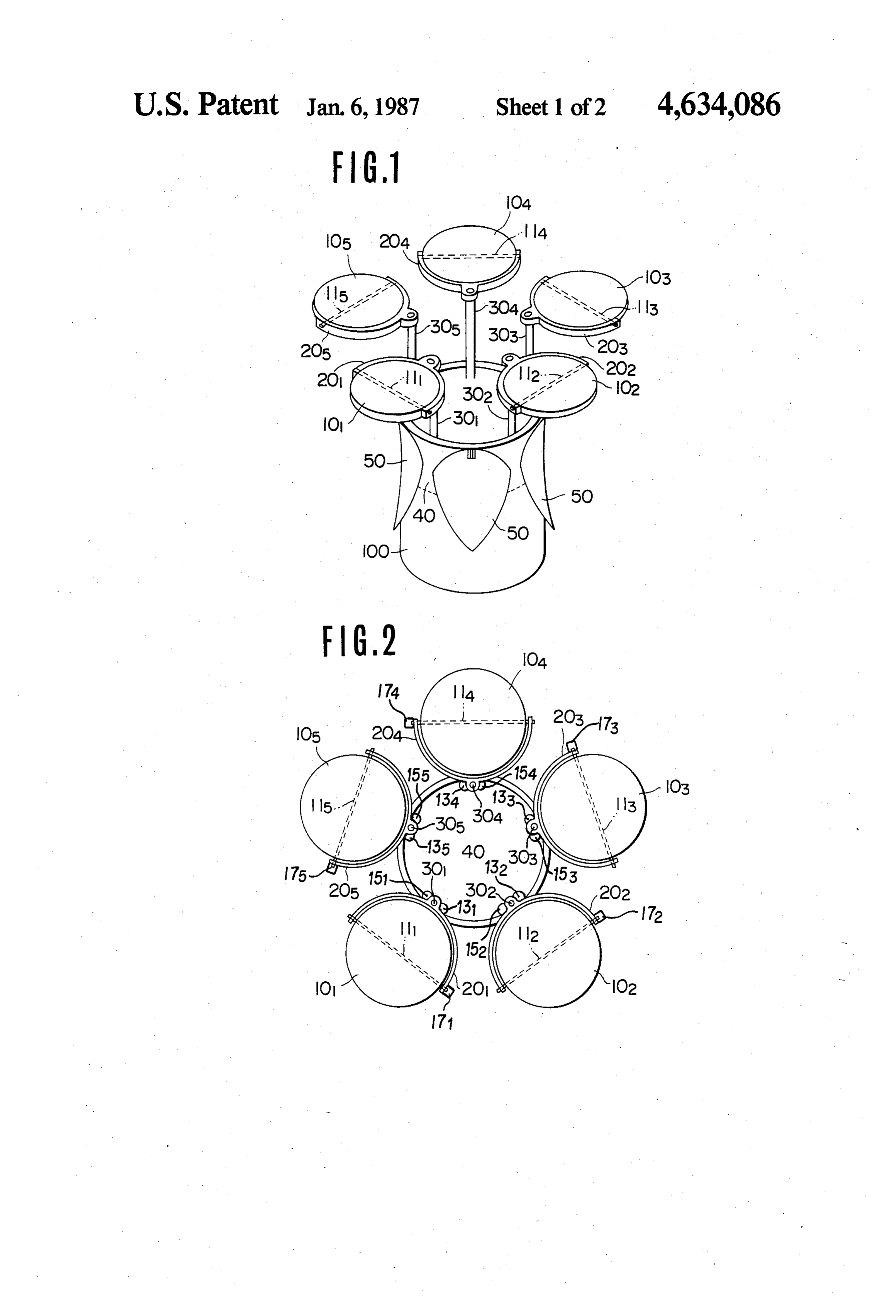
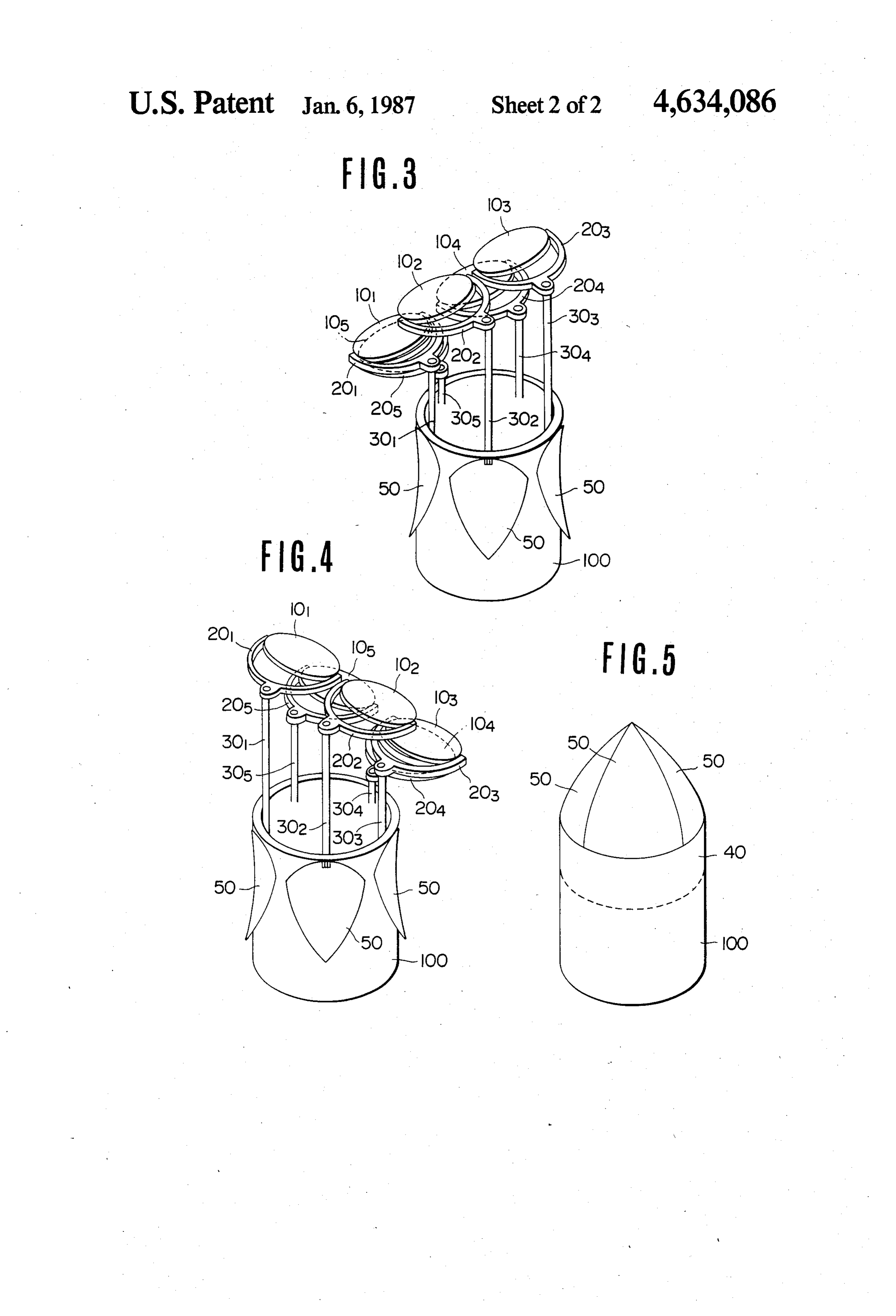
FIG. 2 is a plane view thereof at the time of being
Page 2drawing sheetscan →
Page 3drawing sheetscan →
Page 4scan →
FIG. 2 is a plane view thereof at the time of being
SOLAR RAY COLLECTING DEVICE FOR USE INA employed;
SPACECRAFT FIG. 3 is a perspective view in case that the solar rays come from the left-upper side of the drawing;
This application is a continuation-in-part of applica FIG. 4 is a perspective view in case that the solar rays tion Ser. No. 670,692, filed Nov. 13, 1984, now aban come from the right-upper side of the drawing; and doned. FIG. 5 is a side view of the solar ray collecting device BACKGROUND OF THE INVENTION at the time of not being employed.
The present invention relates to a solar ray collecting 10 DESCRIPTION OF THE PREFERRED device suitable for being loaded and employed in a EMBODIMENTS spacecraft. FIG. 1 is a perspective view for explaining an em The present applicant has previously proposed vari bodiment of the solar ray collecting device according to ous apparatuses and methods by which solar rays are the present invention at the time of being employed. In focused by a lens or the like and guided into an optical 15 FIG. 1, 100 is the outer wall of the spacecraft, 101 conductor, and which are further transmitted through through 105 solar ray collecting portions, 201 through the optical conductor onto an optional desired place for 205 supporting arms for rotatably supporting the solar use in illumination or for other purposes, specifically i.e. ray collecting portions, 101 through 105 respectively, in order to use solar rays as a light source for nurturing 301 through 305 are supporting poles for supporting said chlorella, etc., or as a light source for photosynthesis. 20 supporting arms 201 through 205 respectively at the tip Cosmic engineering has become highly developed in end portion thereof and capable of rotating and moving recent years. As a result of such progress, astronauts are up and down, and 40 a container for accommodating obliged to stay in a spacecraft for longer periods of the solar ray collecting portions and other components time. The supplying of oxygen and food to the astron which is unitarily formed with the spacecraft 100. outs inside the spacecraft arises as one of the most im 25 The supporting poles 301 through 305 are arranged portant problems. As a matter of course, when a rocket rotatably and movably up and down in the container 40, is launched, oxygen containers and an adequate food and each supporting arm 201 through 205 is fixed on the supply are included in the rocket. It is to be expected upper end portion of each supporting pole 301 through that the number of crew members will increase in the future and also the time spent in the spacecraft will 30 305 respectively. Each solar ray collecting portion, 101 increase. At the present time the amount of oxygen and through 105, through is mounted on each supporting arm, 201 food that can be stored in a spacecraft is limited. It is rotatable shaft,so111as through 205, to be able to rotate around each 115, respectively.
clear, according to this invention, that solar rays could Furthermore, as previously proposed by the present be effectively collected for use inside of a spacecraft. applicant, each solar ray collecting Solar rays are the most effective light rays as a source of 35 number of lenses having a diameter ofportion of a large energy for cultivating plant life and for supplying oxy cm and optical fibers, the light-receiving edge surface of4 approximately gen resulting from plant cultivation. which is precisely positioned at the focal point of each SUMMARY OF THE INVENTION lens. The solar rays focused by each lens are guided into It is an object of the present invention to provide a 40 each optical fiber and further transmitted onto an op solar ray collecting device preferable for use in a space tional desired place for use in illumination or for other purposes.
craft or the like which has been launched into space. In the case of employing such a small lens of about 4 It is another object of the present invention to pro vide a solar ray collecting device that is easy to load and cm in diameter, the focal distance of the lens is very use in a spacecraft. 45 small, for instance, about 4 cm. Consequently, it is possi It is another object of the present invention to pro ble made to construct a solar ray collecting device which is very thinly, and therefore which doesn't need vide a solar ray collecting device which is comprised of much space. For this reason, such a solar ray collecting a cylindrical cover, a plurality of round solar ray col device lecting portions, the light-receiving surface of which is comes to saving storageheretofore as mentioned is desirable when it space in a spacecraft.
equal to the cylindrical cover in square measure, sup 50 FIG. 2 is an outlined plan view showing the solar ray porting arms for rotatably supporting the solar ray col lecting portions respectively, and supporting poles, for collecting device according to the present invention at supporting the supporting arms respectively at the tip the time of being employed. When the device is in use end portion thereof and capable of rotating and moving each the supporting poles 301 through 305 for supporting up and down, the solar ray collecting portions being 55 solar ray collecting portion 101 through 105 project taken out from the upper portion of the cylindrical from the cylindrical container 40, and the solar ray cover at the time of being employed and accommodated collecting portion is rotated 180' around the above back into the cylindrical cover at the time of not being mentioned in FIG. 2.
supporting pole and is in the position shown employed.
The above-mentioned features and other advantages A solar ray direction sensor, as previously proposed of the present invention will be apparent from the fol by the present applicant, is installed on each solar ray lowing detailed description which goes with the accom collecting portion. The rotatable shafts, 111 through panying drawings. 115, and the supporting poles, 301 through 30s, are ro tated in accordance with the output signal of the solar
BRIEF DESCRIPTION OF THE DRAWINGS 65 ray direction sensor so that the light-receiving surface FIG. 1 is a perspective view for explaining an em of each solar ray collecting portion is controlled so as to bodiment of the solar ray collecting device according to be always directed in the direction of the solar rays' the present invention; propagation.
Page 5scan →
Under these circumstances, since the front-side solar invention, is loaded onto and employed inside a space ray collecting portion facing the sun projects a shadow craft, the device is not affected by gravity. Therefore, it onto the rear-side solar ray collecting portion, by ad is not necessary to have high-powered energy for mov justing the height of each supporting pole, namely by ing the solar ray collecting portions up and down and controlling the front-side solar ray collecting portion so for rotating them. Furthermore, each solar ray collect as to position it at a place lower than the rear-side solar ing portion can be supported rotatably on one tip end by ray collecting portion, all of the solar ray collecting means of a cantilevered type support as shown in FIGS. portions can collect the sun's rays most effectively. 1 through 4.
FIG. 2 shows electric motor means 131 through 135 As is apparent from the foregoing description, ac which engage the respective supporting poles 301 10 cording to the present invention, it may be possible to through 305 for rotating the supporting poles 30 provide a solar ray collecting device which is light, through 305. FIG. 2 also shows electric motor means efficient, and convenient for loading and employing in a 151 through 155 which engage the respective supporting spacecraft.
poles 301 through 305 for longitudinally extending and What is claimed is:
withdrawing the supporting poles 301 through 305. 15 1. A solar ray collecting device loaded and employed FIG. 2 further shows electric motor means 171 through in a spacecraft comprising a cylindrical container, a 175 for rotating the respective shafts 111 through 115. plurality of round solar ray collecting portions each Namely, when the solar rays come from the left having a light-receiving surface, each of said light upper side of FIG. 3, the left side solar ray collecting receiving surfaces having a surface area substantially portion is situated at the lower place while the right side 20 equal to the circular cross-sectional area of the cylindri solar ray collecting portion is situated at the upper cal container, supporting arms for rotatably supporting place, as shown in FIG. 3. On the contrary, when the each of said solar ray collecting portions, and support solar rays come from the right-upper side of FIG. 3, the ing poles supporting each of said supporting arms, said right side solar ray collecting portion is situated at the supporting poles being rotatable to thereby rotate said lower place while the left side solar ray collecting por 25 supporting arms and the solar ray collecting portion tion is situated at the upper place as shown in FIG. 4 so supported on the respective supporting arm about the that all of the solar ray collecting portions are con axis of the respective supporting pole, said supporting trolled in order to consistently collect the solar rays. poles being longitudinally moveable to longitudinally With respect to changing the solar ray collecting de extend and withdraw said supporting arms and the solar vice's height, when the solar rays come from right over 30 ray collecting portions supported on the respective head, or in other words when the solar ray collecting supporting arm, whereby said solar ray collecting por portions, 101 through 105, are in the state as shown in tions are movable into a non-deployed position in which FIG. 2, all of the solar ray collecting portions are ex the solar ray collecting portions are accommodated changed with the others simultaneously. In such a man within said cylindrical container and a deployed posi ner, there is no fear that the solar ray collecting portion 35 tion in which said solar ray collecting portions are dis comes into contact with any other part. As a result the posed outside of said cylindrical container for collecting height thereof can be smoothly adjusted with the oth solar rays.
erS. 2. A solar ray collecting device according to claim 1, In the state as shown in FIG. 4, when the solar ray wherein there are five of said solar ray collecting por collecting portions are being accommodated in the con tions.
tainer, first the solar ray collecting portions are rotated 3. A solar ray collecting device according to claim 1, 180' in order around the supporting poles thereof start wherein a lid means for opening and shutting said cylin ing from the upper solar ray collecting portions, and drical container is provided on the upper end portion of secondly all of the solar ray collecting portions are said cylindrical container.
accommodated in the container 40 by contracting the 45 4. A solar ray collecting device according to claim 3, respective supporting poles into the container 40. Each wherein said lid means comprises a plurality of lid mem solar ray collecting portion, 101 through 105, is con bers pivotably mounted on said cylindrical container. structed so as to fit the shape of the container 40. In the 5. A solar ray collecting device according to claim 1, case of the embodiment as shown in FIG. 4, the solar wherein said supporting arms each have a generally ray collecting portion is formed in a round shape. The 50 C-shaped configuration having two terminating end diameter D of the solar ray collecting portion is de sections and a central section, and means on said end signed so as to make it as large as possible in consider sections for rotatably supporting said round solar ray ation of the position of the supporting pole in the con collecting portions for rotation about a diametrical axis. tainer and with respect to the total light-receiving 6. A solar ray collecting device according to claim 5, square measure versus the accommodation square mea 55 further comprising means for mounting said supporting sure. On that occasion, five solar ray collecting devices poles on the respective central section of said support can be most effectively arranged in a neighboring area ing arms.
around the accommodating cylinder as shown in FIG. 7. A solar ray collecting device according to claim 1, 4. whereby all of said round solar ray collecting portions FIG. 5 is a perspective view of the embodiment at the are disposed in overlying and aligned relationship when time of not being in use. When the solar ray collecting in said non-deployed position in said cylindrical con device is not being employed, the cover 50 covers and tainer.
shuts off the cylindrical container in order to protect 8. A solar ray collecting device according to claim 1, the solar ray collecting portions contained therein from wherein motor means are provided on each of said being destroyed from dust, etc., as shown in FIG. 5. 65 supporting arms for rotating the respective round solar The solar ray collecting device according to the pres ray collecting portions about an axis coinciding with a ent invention has been described heretofore. Since the diametrical line passing through the center of the re solar ray collecting device according to the present spective round solar ray collecting portions.
Page 6scan →
9. A solar ray collecting device according to claim 1, rotating said supporting arms and the solar ray collect wherein motor means are provided for each of said ing portion supported on the respective supporting arm supporting poles for longitudinally extending and with about the axis of the respective supporting pole, third drawing the respective supporting pole. motor means provided for each of said supporting poles 10. A solar ray collecting device according to claim for longitudinally extending and withdrawing the re 1, wherein motor means are provided for each of said spective supporting pole, said supporting poles being supporting poles for rotating each of said supporting thereby longitudinally movable to longitudinally extend poles about the axis of each respective supporting pole. and withdraw said supporting arms and the solar ray 11. A solar ray collecting device loaded and en collecting portions supported on the respective support ployed in a spacecraft comprising a cylindrical con 10 ing arm, whereby said solar ray collecting portions are tainer means, a plurality of round solar ray collecting portions each having a light-receiving surface, each of movable into a non-deployed position in which the solar ray collecting portions are accommodated within said said light-receiving surfaces having a surface area sub cylindrical container means and a deployed position in stantially equal to the circular cross-sectional area of the which said solar ray collecting portions are disposed cylindrical container means, supporting arms for rotat 15 ably supporting each of said solar ray collecting por outside of said cylindrical container for collecting solar tions, said supporting arms each having a generally disposed inround rays, said solar ray collecting portions being overlying and aligned relationship when in
C-shaped configuration having two terminating end said non-deployed position in said cylindrical container sections and a central section, rotatable support means means, and lid means comprising a plurality of lid mem on said end sections for rotatably supporting said round 20 bers pivotably mounted on said cylinder container solar ray collecting portions for rotation about a diamet rical axis, first motor means on said supporting arm for means for opening said cylinder container means to rotating said round solar ray collecting portions about provide for moving said solar ray portions into said said diametrical axis, supporting poles supporting each deployed position and for closing said container means of said supporting arms, second motor means provided 25 when said solar ray collecting portions have been for each of said supporting poles for rotating each of moved into said non-deployed position within said cy said supporting poles about the axis of each respective lindrical container means.
supporting pole, said rotatable supporting poles thereby k k
Provenance
- Collection
- Patents citing this work
- Pages
- 6
- Method
- pdftotext (the PDF's own text layer) + pdftoppm 300dpi page scans
- Patent office record
- patents.google.com →
- Source
- Google Patents citing-documents table
- Assignee
- Kei Mori
- Published
- 1987-01-06
- Transcribed from
- patentimages.storage.googleapis.com →