

patent · US4537180A
Solar heating and storage unit
27 August 1985
Text
Page 1bibliographic recordscan →
United States Patent (19)
Minor
54 SOLAR HEATING AND STORAGE UNIT
(76. Inventor: John W. Minor, 173 Dolphin Ave.
SE., St. Petersburg, Fla. 33705
Related U.S. Application Data
doned.
51 Int. Cl.................................................. F24J 3/02 (52) U.S. C. ..................................... 126/437; 126/450
1,093,498 4/1914. Thring ................................. 26/271 1,575,309 3/1926 Anderson .. ... 126/438 2,167,576 7/1939 Kiser ..... ... 126/443 2,213,894 9/1940 Barry ................................... 126/443
3,587,559 6/1971 Nonaka ............................... 126/440 4,056,093 11/1977 Barger ... ... 126/271 4,057,048 11/1977 Maine ............ ... 126/440 4,116,223 9/1978 Vacilantone .. ... 126/271 4,236,507 12/1980 Vincent ............. s so a - a 126/450
4,344,418 - 8/1982 Leroy .................................. 126/450 4,346,696 8/1982 Brunet ................................. 26/450
FOREIGN PATENT DOCUMENTS
2468077 4/1981 France ................................ 126/437
Primary Examiner-Carroll B. Dority, Jr.
Attorney, Agent, or Firm-Woodcock, Washburn,
Kurtz, Mackiewicz & Norris
A hemispherically shaped solar heater and storage unit comprises an insulated base, a hemispherically shaped inner dome having a surface capable of absorbing solar energy, and attached to the base to form a reservoir capable of withstanding a preselected pressure, a sub stantially transparent hemispherically shaped outer dome having a diameter larger than the inner dome and positioned over the inner dome, means for introducing a fluid under pressure into the bottom area of the reser voir, a diffuser for introducing the fluid into the reser voir without substantially disturbing the fluid at the top of the reservoir, and means for removing heated fluid from the top of the reservoir.
12 Claims, 7 Drawing Figures
Drawings
Page 2drawing sheetscan →
Page 3drawing sheetscan →
Page 4scan →
connected transparent lenses for Ening a dome-shaped
SOLAR HEATING AND STORAGE UNIT roof for receiving direct solar radiation and for trans mitting such radiation through the lenses into the enclo
This is a continuation of application Ser. No. 313,270, sure formed thereby and focusing it onto a shallow tray filed Oct. 21, 1981 and now abandoned. of water forming a floor of the enclosure. The invention relates to a solar device for the heating U.S. Pat. No. 4,116,223 to Vasilantone teaches a solar and storing of a heat absorbing fluid such as water and energy unit comprising a housing adapted to be more particularly to a hemispherically shaped unit mounted on the roof of a building or otherwise suitably which retains thermal energy with minimal thermal supported. The housing has a central cavity which con loss. The solar heater and storage unit of this invention 10 tains a reservoir for a heat absorbing liquid. A heat is adaptable for use in series with a domestic hot water exchanger containing a circulating heat exchange fluid System. is immersed in the heat-absorbing liquid. The heat ex BACKGROUND AND OBJECTS OF THE change fluid circulates to areas to be heated. A substan INVENTION tially hemispherical and transparent dome covers the 5 upper end of the housing and the cavity and is provided
A variety of solar devices have been proposed, many with prismatic facets on its inner surface to magnify the of which have flat plate collectors that require pumps, sun's rays and to focus or concentrate the rays on the electronic controls, and additional water storage which heat-absorbing liquid.
may include increasing the capacity of conventional U.S. Pat. No. 4,236,507 to Vincent teaches a solar electrical heaters used as part of a hot water system. 20 heater for air. The solar heater has a shape like a dome The efficiency of such flat plate systems may also be with a transparent outer cover and transparent inner affected by the angle at which the sun hits the plate. cover. A dead air layer is inbetween covers. Inside the Thus, the plate may have to be mechanically or manu done is a collector that holds up the covers and con ally turned to obtain full exposure to the sun's rays. verts the solar rays to heat. Air or gas is circulated Attempts have been made to overcome this angle orien 25 through the solar heater from an input pipe on one side tation problem. to an output pipe on the other side, obtaining heat from U.S. Pat. No. 4,256,092 to Gutermuth et al. shows a the collector and base by conduction and radiation. solar radiation converter which includes a black insu There is thus a need for a unified solar heater and lated housing with a front glass wall and a plurality of storage system which can function as a passive system blackened rotationally symmetrical balls or cylinders 30 without the requirements of pumps and/or expensive pivotally disposed within the housing as absorber ele electronics, and which is adaptable for use with a do ments and turned by a flowing heat transfer medium mestic hot water system.
such as water. It is, therefore, an object of the present invention to U.S. Pat. No. 3,587,559 to Nonaka teaches an appara provide a unitary solar heating and storage unit capable tus for heating water by solar rays comprising a plural 35 of providing hot water for home and/or industrial use. ity of spherical lenses positioned in a box covered by It is a further object of this invention to provide a glass at the side facing the sun, a plurality of heat col solar heating and storage unit which does not have to be lecting members each positioned below each of the adjusted to any change in the angle of exposure to the spherical lenses, each of the heat collecting members Sull.
being lined with a superheat resisting carbon impreg 40 It is yet another object of this invention to provide a nated cloth at the area subjected to focused rays, and a solar heater and storage unit which minimizes heat loss continuous water pipe extending in a number of convo to the atmosphere.
lutions within the box. It is a further object of this invention to provide a U.S. Pat. No. 4,056,093 to Barger discloses a solar solar unit which will reduce the cost of using solar heating unit including an upwardly opening generally 45 energy.
hemispherical double wall boiler including spaced inner and outer hemispherical walls defining a closed cham SUMMARY OF THE INVENTION ber therebetween in which to receive a liquid to be The solar heater and storage unit of this invention heated. An upwardly convex spherical lens structure is comprises an insulated base structure, a hemispherically supported over the boiler and comprises a closure for 50 shaped inner dome having a surface capable of absorb the area enclosed within the boundaries of the inner ing solar energy and attached to the base to form a hemispherical wall of the boiler and the lens assembly reservoir capable of withstanding a preselected pres or structure functions to direct light rays incident sure, a substantially transparent hemispherically shaped thereon onto the inner wall of the boiler. The solar outer dome having a diameter larger than the inner heater additionally includes a hollow downwardly 55 dome and positioned over the inner dome, means for opening transparent hemispherical cover of generally introducing a fluid under pressure into the bottom area the same radius of curvature as the boiler and which is of the reservoir, a diffuser for introducing the fluid into secured over the lens assembly in outwardly spaced the reservoir without substantially disturbing the fluid position relative thereto with the center of curvature of at the top of the reservoir, and means for removing the cover substantially coinciding with the center of 60 heated fluid under pressure from the top of the reser curvature of the lens assembly. Water or other liquid voir. Preferably at least one excess pressure relief means inlet and outlet structure is provided on a second form is also included. Additionally other pressure regulating of the invention for admitting liquid to be heated into means may also be employed. In operation solar energy the interior of the boiler between the inner and outer is transmitted through the outer dome and absorbed by plates thereof and for withdrawing heated liquid from 65 the surface of the inner dome. This process heats water within the boiler. which has been introduced into the reservoir. The hot U.S. Pat. No. 4,057,048 to Maine discloses a solar ter water rises to the top of the reservoir where it may heat-collecting structure comprising a series of inter be withdrawn on a demand basis.
Page 5scan →
Brief description of the drawings
Exit means 12, e.g. a pipe, is positioned below the Sur face of the water. A safety feature in the form of a relief
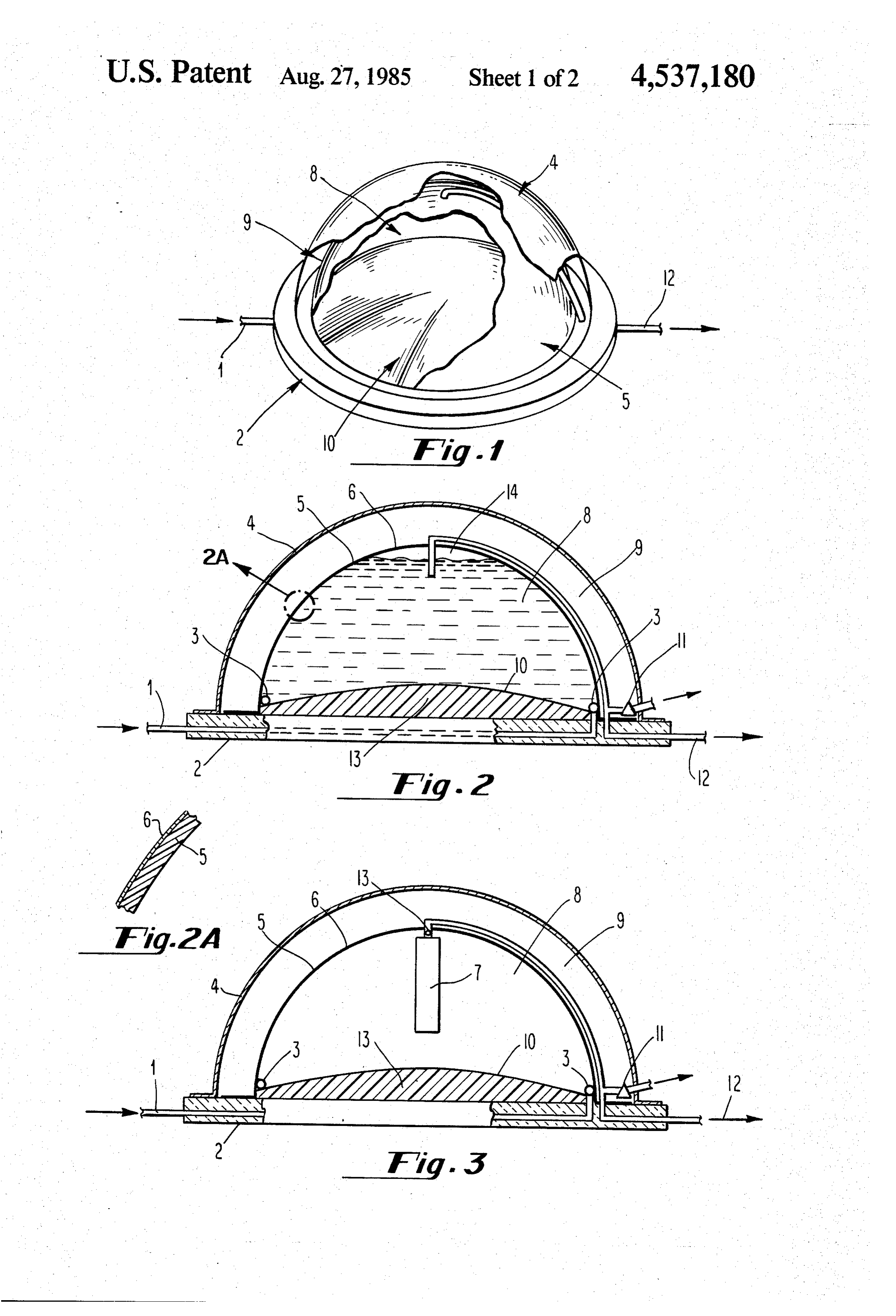
FIG. 1 is a general perspective view of a solar heater valve 11 is positioned in exit line 12 so that excess pres and storage apparatus constructed in accordance with sure and/or heated water may be released. Relief valve this invention, with portions of the outer and inner 5 11 may be vented to the atmosphere. domes cut away; FIG. 2a shows an enlarged fragmentary section of FIG. 2 is a sectional view of a solar heating and stor the inner dome 5 and shows a solar energy absorbing age unit constructed in accordance with this invention; surface 6.
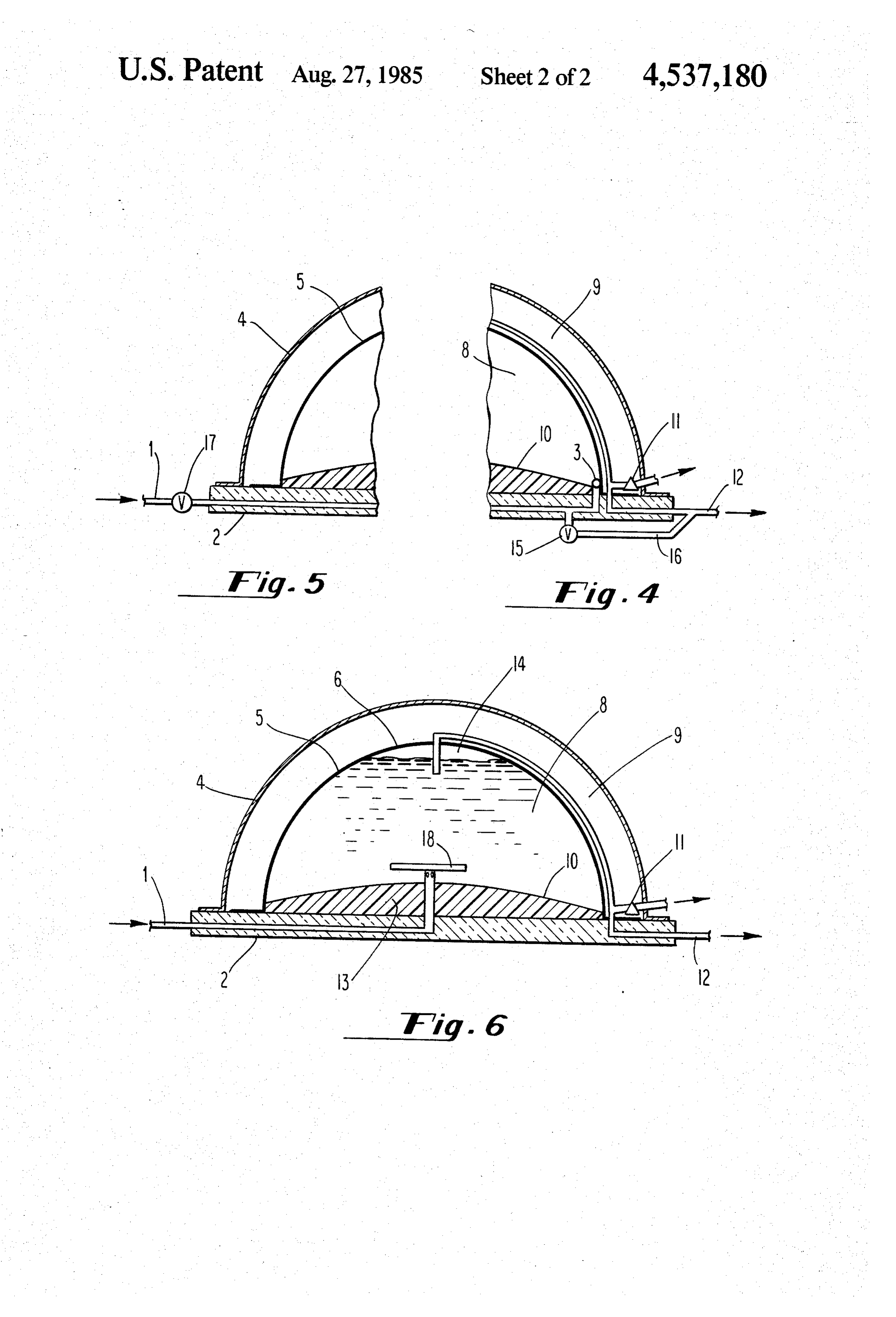
FIG. 2a is an enlarged fragmentary view of a section FIG. 3 shows an alternate embodiment of the inven of the inner dome; O tion which includes a water expansion accumulator 7. FIG. 3 is a sectional view of an alternate embodiment The accumulator 7 is closed at the top end and initially of the invention containing a water expansion accumu contains air. Upon expansion of the water contained in lator; reservoir 8, the water may compress the air contained in FIG. 4 is a fragmentary view of an embodiment of the accumulator 7 to accommodate this expansion. Accu invention containing a pressure valve positioned in the 15 mulator 7 may be suspended in reservoir 8 by means of cold water line and vented into the hot water exit line; attachment to one end of exit pipe 12. In this embodi FIG. 5 is a fragmentary section showing an alterna ment the end of exit pipe 12 which is attached to accu tive pressure control means positioned in the cold water mulator 7 which pipe has at least one substantial perfo line to regulate the pressure of the cold water as it en ration 13 therethrough to allow the heated water to exit ters the unit; through the exit pipe 12.
FIG. 6 is a sectional view of another embodiment of FIG. 4 is a fragmentary view of a pressure releasing this invention in which a diffusion plate is used as the means located within the inlet line 1. This pressure diffuser. releasing means is a valve switch 15 set at a preselected DETAILED DESCRIPTION OF THE pressure. If the inlet water exceeds this pressure, water 25 is vented by means of line 16 into the hot water exit 12
DRAWINGS until the pressure falls below the preselected limit. FIG. 1 is a general perspective view of a solar heater FIG. 5 shows an alternative pressure regulating and storage unit constructed in accordance with this means in the form of a series valve impedence 17. This invention and shows the overall hemispheric shape of impedence may be used to regulate the pressure of the the unit. The interior of the unit comprises an insulated 30 fluid before it enters the reservoir 8, and is preferably base 2 with a bottom 10 over which is positioned a positioned proximate to where the source of fluid, e.g. hemispherically shaped inner dome 5 to form a reser cold water, is attached to cold water line 1, but before voir area 8. Inner dome 5 has a surface 6 adapted for the cold water enters the unit.
absorbing solar energy (e.g. dark colored paint) and is FIG. 6 shows another embodiment comprising an attached (e.g. welding or gluing) to insulated base 2 so 35 alternative diffuser. The alternative diffuser structure is as to form a substantially water tight seal. Optionally a shown as a plate 18 under which the cold water from gasket may be used to achieve a good seal. A hemi line 1 enters reservoir 8 through perforations 19 in line spherically shaped outer dome 4 having a diameter 1 and is deflected off of the bottom of plate 18. larger than inner dome 5 is positioned over the interior The hemispheric shape of the unit provides optimum structure thereby creating a gap 9 between the two 40 strength and volume as well as maximizing the absorp domes. This gap may contain air or be partially evacu tion of solar energy.
ated. An inlet 1 is positioned in base 2 for introducing The solar heater and storage unit of this invention water into reservoir 8. As the sun's light and energy may be constructed from a variety of materials and in a passes through the substantially transparent outer dome variety of sizes. As previously explained the inner dome 5, the solar radiation is absorbed by the surface of inner 45 5 is attached to bottom 10 to form a reservoir 8. The dome 5 and heats the water contained in reservoir 8. inner dome and bottom may be made from metal or The hotter water rises to the top of reservoir 8 by a plastic depending on the pressure which the system convection process and may be removed on demand must withstand. Due to safety codes, a system usually through exit means 12 which has one end positioned must be made to withstand pressures of about 160 proximate to the top of reservoir 8 through inner dome 50 lb/in2. When pressure regulating means such as those 5 and the other end vented into an end system or collec shown in FIGS. 4 or 5 are used, a lower pressure may tor, e.g. a domestic heating system. A major portion of be selected (e.g. 80 lb/in2) and maintained, thus allow exit line 12 is preferably positioned withingap 9 so as to ing manufacturing costs to be decreased without sacri take advantage of this insulating area. ficing safety requirements. Means of attaching various FIG. 2 is a sectional view of one embodiment of a 55 components to each other may include welding and/or solar heater and storage unit constructed in accordance gluing.
with this invention. The insulated base 2 is shown with The unit may be constructed in a variety of dimen bottom 10 over an insulating layer 13, e.g. foam. Inlet 1 sions. For a domestic unit a capacity of about 165 gal is positioned in base 2 and attached to a diffuser 3. In lons for the reservoir is preferred. It is preferred that the this embodiment diffuser 3 may be a perforated pipe 60 gap 9 between the domes be about 7 inches in a unit of positioned around the interior circumference of bottom this size.
10. Preferably the perforations in the pipe are positioned The solar heater and storage collector may be to allow water to enter reservoir 8 at proper angles and mounted on a dirt embankment and connected to supply without displacing the hot water at the top of the reser domestic hot water needs such as for heating or bathing. voir 8. The diffuser reduces turbulance which may 65 It is a passive apparatus and needs no support pumps or result from introducing cold water into reservoir 8. electronic components.
FIG. 2 shows reservoir 8 with an air gap 14 at the top The embodiments described herein are merely illus to allow for expansion upon the heating of the water. trative of the invention. Numerous modifications in 6 cluding various combinations of the above described 6. The solar heater and storage unit of claim 5 structures will readily occur to those skilled in the art. wherein said pressure regulating means comprises a Thus other modifications and changes may be made relief valve positioned in said exit means. which are within the spirit and scope of the invention. 7. The solar heater and storage unit of claim 5 I claim: wherein said pressure regulating means comprises a 1. A solar heater and storage unit comprising: series valve impedence structure. an insulated base structure, 8. The solar heater and storage unit of claim 5 a hemispherically shaped inner dome having a surface wherein said pressure regulating means comprises a capable of absorbing solar energy and attached to pressure valve positioned in said introducing means and said base to form a reservoir capable of withstand 10 vented into said exit means.
ing a preselected pressure, 9. The solar heater and storage unit of claim 1 a substantially transparent hemispherically shaped wherein said introducing means is a pipe. outer dome having a diameter larger than said 10. A method for heating water comprising: inner dome and positioned over said inner dome, introducing water under pressure into a solar heater means for introducing a fluid under pressure into the 15 and storage unit through an insulated base struc bottom area of said reservoir, ture, said unit having a hemispherically shaped a diffuser, said fluid being introduced into said reser inner dome positioned on said base with a substan voir through said diffuser without disturbing the tially watertight seal to form a reservoir, said inner fluid at the top of said reservoir, and dome having a solar energy absorbing surface, exit means for removing heated fluid under said pres diffusing said water under pressure into said reservoir sure from the top of said reservoir. without disturbing water at the top of said reser 2. The solar heater and storage unit of claim 1 voir, wherein said fluid is water. exposing said inner dome to solar radiation through a 3. The solar heater and storage unit of claim 1 substantially transparent hemispherically shaped wherein said insulated base comprises a metallic bottom 25 outer dome having a diameter larger than said positioned over insulation. inner dome and placed over said inner dome, and 4. The solar heater and storage unit of claim 1 withdrawing heated water under said pressure from wherein said diffuser comprises a perforated pipe posi the top of said reservoir. tioned at about the bottom area of said reservoir and 11. The solar heater and storage unit of claim 1 which proximate to the interior circumferential edge of said 30 additionally comprises a water expansion accumulator. base. 12. The solar heater and storage unit of claim 4 which 5. The solar heater and storage unit of claim 1 which additionally comprises a water expansion accumulator. additionally comprises a pressure regulating means. k k ck k
Provenance
- Collection
- Patents citing this work
- Pages
- 6
- Method
- pdftotext (the PDF's own text layer) + pdftoppm 300dpi page scans
- Patent office record
- patents.google.com →
- Source
- Google Patents citing-documents table
- Assignee
- Minor John W
- Published
- 1985-08-27
- Transcribed from
- patentimages.storage.googleapis.com →