

patent · US4703749A
Solar apparatus
3 November 1987
Text
Page 1bibliographic recordscan →
United States Patent (19)
Morse
54). SOLAR APPARATUS
76 Inventor: Roger N. Morse, 464 Kooyong Road,
Caulfield, Victoria, Australia
Related U.S. Application Data 63 Continuation of Ser. No. 700,333, Feb. 12, 1985, aban doned, which is a continuation of Ser. No. 536,510,
30 Foreign Application Priority Data Sep. 30, 1982 Australia ............................... PF6141 51 Int. Cl. ................................................. F24J 2/00 52 U.S. Cl. .................................... 126/436; 126/400;
3,812,903 5/1974 Thomason ..... ... 126/400 3,919,998 11/1975 Parker ........... ... 126/435 3,960, 136 6/1976 Moan et al. ....... ... 126/443 3,980,130 9/1976 Thomason et al. ... 126/400 3,993,041 11/1976 Diggs ................ ... 126/435 4,037,583 7/1977 Bakun ..... ... 126/430 4,051,891 10/1977 Harrison. 65/DIG. 4 4,054,124 10/1977 Knoos .... - 26/435 4,076,025 2/1978 Parker ... ... 126/435 4,081,024 3/1978 Rush et al. ........ ... 126/436 4,133,298 1/1979 Hayama ............ ... 126/443 4, 137,898 2/1979 Koizumi et al. ... 126/400 4,139,321 2/1979 Werner .......... ... 126/400 4,173,304 1/1979 Johnson ..... ... 126/400 4,186,725 2/1980 Schwartz ... ... 126/443 4,187,831 2/1980 Eubank ... ... 126/435 4,196,719 4/1980 Skriuseth .... ... 126/400 4,222,365 9/1980 Thomson ....... ... 126/436 4,231,353 1 1/1980 Kanatani et al. ... 120/443 4,244,519 1/1981 Zornig et al. .. ... 26/400 4,270,600 6/1981 Bourden ..... ... 126/435 4,279,242 7/1981 Bogatzki. ... 126/443 4,284,066 8/1981 Brow ...... ... 126/435 4,286,575 9/1981 Gates ...... ... 126/430 4,289,117 9/1981 Butcher. ... 126/435 4,29,680 9/1981 White .................................. 126/443 4,291,833 9/1981 Franchina ........................... 126/400
4,303,058 12/1981 Chum .................................. 126/436 4,346,694 8/1982 Moan .......... ... 26/443 4,421,099 12/1983 Van der Aa 126/443 4,434,785 3/1984 Knudsen ............................. 126/400 4,444,249 4/1984 Cady .............................. 65/104.11 4,515,149 5/1985 Sgroi et al........................... 126/443 4,526,225 7/1985 Stanton ...... ... 126/400 4,535,755 8/1985 Roberts ............................... 126/443
FOREIGN PATENT DOCUMENTS
0095544 6/1982 Japan ................................... 126/443
OTHER PUBLICATIONS
"The Performance of Solar Air Heater and Rockpile
Thermal Storage System', Choda et al., 1970 Int’l. Solar Energy Society Conference (Australia, 1970). Primary Examiner-Samuel Scott
Assistant Examiner-H. A. Odar
Attorney, Agent, or Firm-Schwartz, Jeffery, Schwaab, Mack, Blumenthal & Evans
An improved solar apparatus for heating above 100C. is disclosed. Said apparatus comprises a solar collector means for heating a heat transferring gas, ducting means extending from said solar collector means for permit ting moving of said gas past a heat storage medium whereby heat in said gas will be transferred to said heat storage medium by directly contacting said heat storage medium, flow control means provided in said ducting whereby to permit said gas to flow to said heat storage medium when said solar collector means is radiated by the sun, and to permit said gas to pass through said heat storage medium for recovery of heat therefrom when said solar collector means is not radiated by the sun. The solar collecting means includes a plurality of col lectors, each collector comprising two elongate concen tric tubes connected together at each end to provide an annular space therebetween, said annular space being evacuated and wherein the outer surface of the inner tube has a selective surface to enhance solar energy absorption, said inner tube providing a passageway for said gas to be heated by said collector, and wherein said plurality of collectors are interconnected with others at their ends and to said ducting means so that said gas can pass therethrough and be heated and then passed into said ducting means at a temperature in excess of 100 C. 18 Claims, 5 Drawing Figures
Drawings
Page 2drawing sheetscan →
Page 3drawing sheetscan →
Page 4scan →
Most preferably each end of the collector tube is
SOLARAPPARATUS mounted within an annular connector support member of thermally insulating material. It is particularly pre
This is a continuation of application Ser. No. 700,333, ferred that the connector support be for connecting filed Feb. 12, 1985, which was abandoned upon the other similar collectors end to end to provide a series air filing hereof, which is a continuation of Ser. No. path through the inner tubes. 536,510 filed Sept. 28, 1983 now abandoned. It is particularly preferred that the gas which is heated be air although other gases which have desired
BACKGROUND OF THE INVENTION heat transference properties may be used. 1. Field of the Invention 10
Brief description of drawings
This invention relates to solar apparatus and relates In order that the invention can be more clearly ascer particularly but not exclusively to such for providing tained preferred embodiments for generating steam will heat at 100° C. or higher. now be described with reference to the accompanying 2. Description of Prior Art
Hitherto steam has been generated by solar means by 15 drawings wherein:
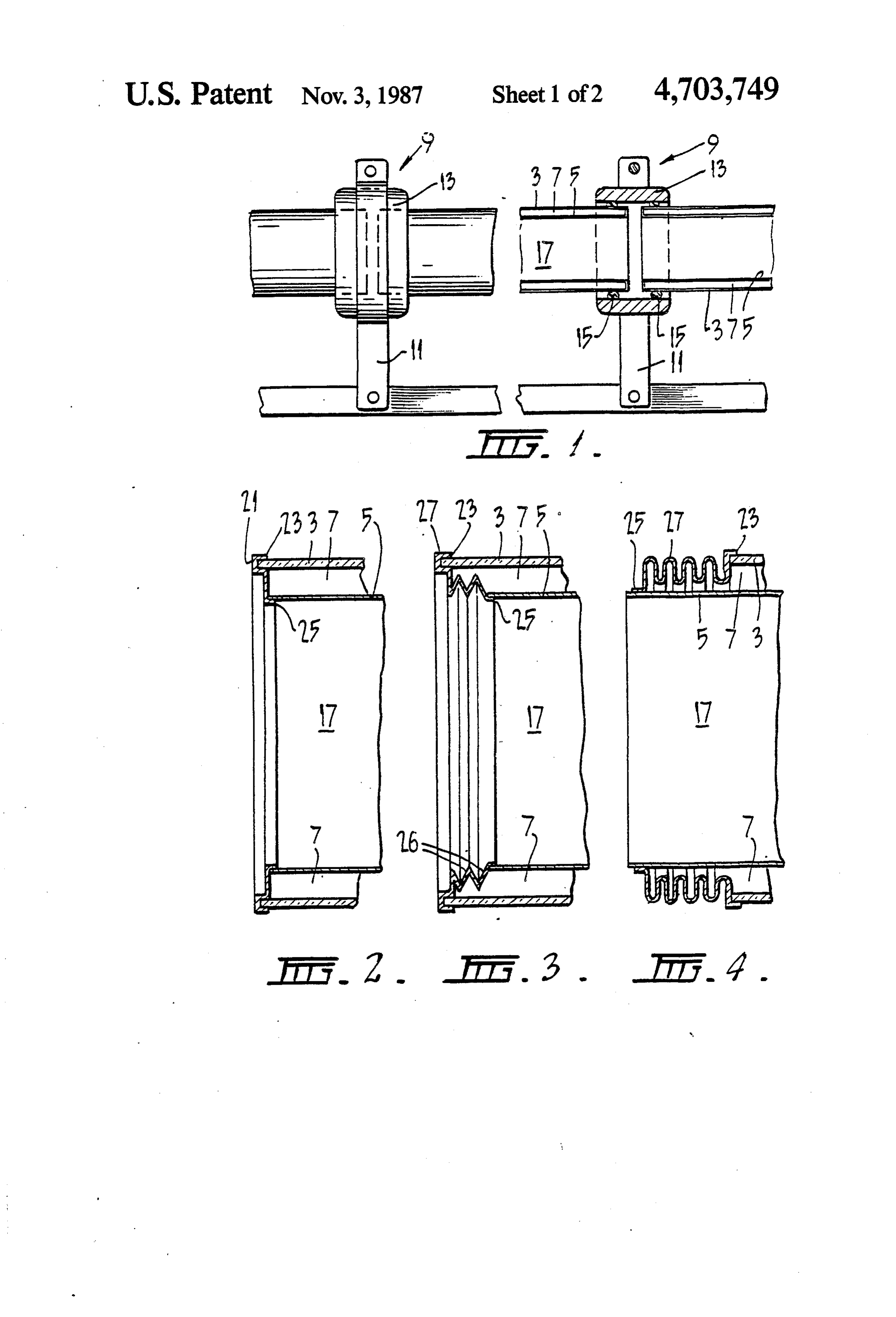
directly heating water in a solar collector. However ofFIG. 1 is a side view of a preferred solar collector and a preferred connector support means used for con with such heating it is not economically feasible to store the steam for subsequent use. The present invention necting FIG.
a plurality of such solar collectors in series; , 2 is an enlarged vertical section of one end of a attempts to provide solar apparatus where a gas such as air is heated to above 100° C. and in one embodiment 20 seal at one of the tubes shown in FIG. 1; FIG. 3 is an enlarged vertical section of a further then used to convert water to steam and whereby en embodiment of seal at one end of the tubes shown in ergy from the solar collectors therein can be stored in a FIG. 1;
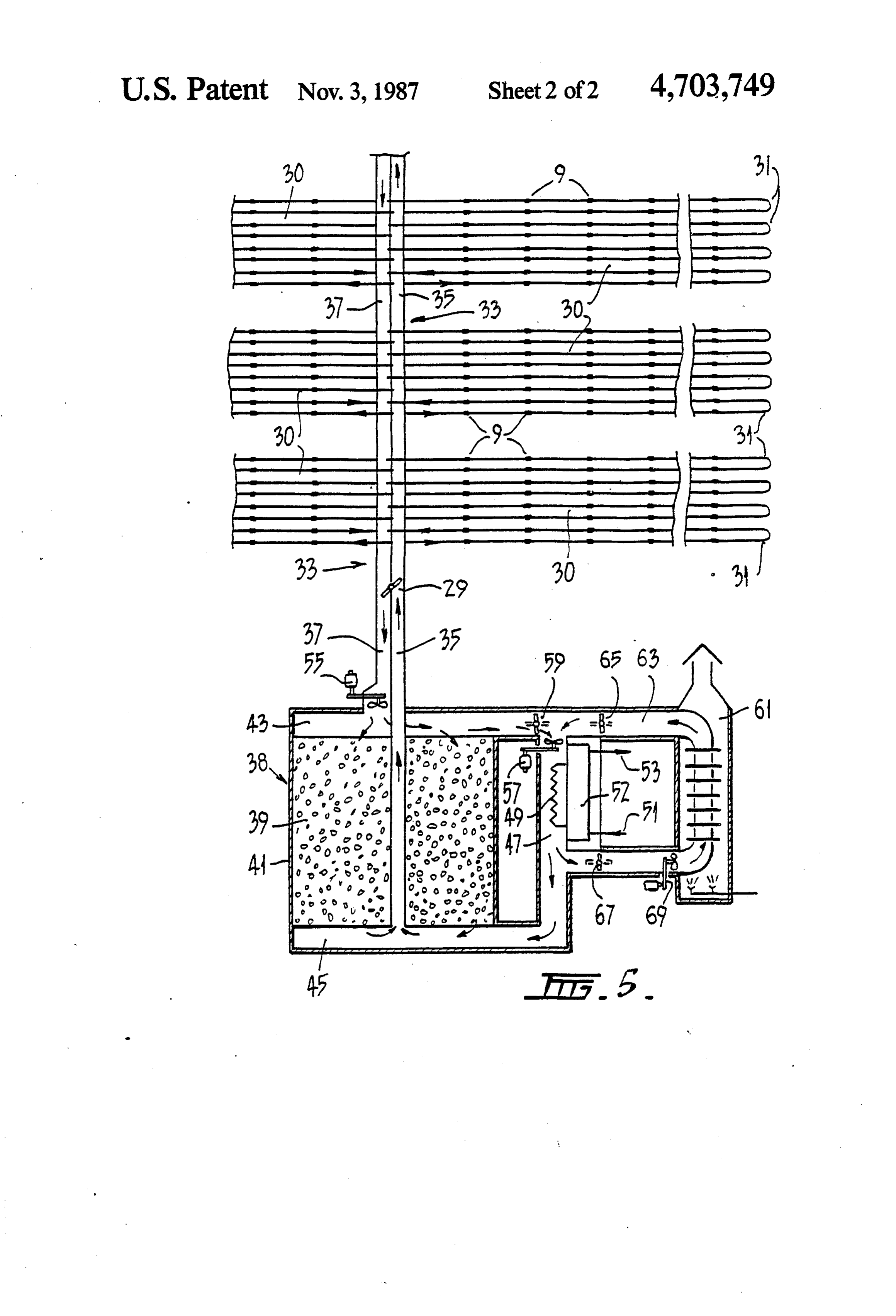
suitable store and then transferred from that store to FIG. 4 is an enlarged vertical section of a further provide steam at a subsequent time as for example when 25 embodiment of seal at one end of the tubes shown in the collectors are unable to be radiated by the sun. FIG. 1; and
STATEMENT OF THE INVENTION FIG. 5 is a schematic diagram of a typical solar appa It is an object of the invention to provide an im ratus made in accordance with the present invention. proved solar apparatus which will provide heat at 100 30 DESCRIPTION OF PREFERRED EMBODIMENT C. or above. Referring firstly to FIG. 1 there is shown a solar Therefore in accordance with a broad aspect of the collector 1 comprising a pair of elongate tubes 3 and 5 present invention there may be provided an improved mounted one within the other. The outer tube 3 is of solar apparatus for heating above 100° C., said appara glass and the inner tube 5 of metal. The tubes 3 and 5 are tus comprising a solar collector means for heating a heat 35 mounted coaxially so that an annular space 7 is pro transferring gas, ducting means extending from said vided therebetween. The annular space is evacuated of solar collector means for permitting moving of said gas air and each end of the collector 1 is sealed, thereby past a heat storage medium whereby heat in said gas providing a sealed evacuated annular space 7. The outer will be transferred to said heat storage medium by di surface of the inner tube 5 is coated with a selective rectly contacting said heat storage medium, flow con 40 absorbing surface such as nickel-black which may be trol means provided in said ducting whereby to permit deposited by one of the known conversion coating pro said gas to flow to said heat storage medium when said cesses for solar collectors. A typical method is disclosed solar collector means is radiated by the sun, and to in Solar Energy Materials 5 (1981) 317-355-North permit said gas to pass through said heat storage me Holland Publishing Co.-by K.J. Cathro-Formation of dium for recovery of heat therefrom when said solar 45 Nickel-Black Selective Surfaces by A Conversion Coat collector means is not radiated by the sun. ing Process. The glass used for the outer tube 3 is selected It is also preferred that said solar collecting means to have a high solar transmittance and may be coated includes a plurality of collectors, each collector com with one of the known anti-reflecting coatings to further prising two elongate concentric tubes connected to improve the solar transmittance. The collector 1 is gether at each end to provide an annular space therebe 50 constructed to ensure that thermal stresses caused by any tween, said annular space being evacuated and wherein temperature differentials between the inner and outer the outer surface of the inner tube has a selective surface tubes 3 and 5 do not result in rupture of a tube. A typical to enhance solar energy absorption, said inner tube length of the solar collector 1 is 1500 mm long with the providing a passageway for said gas to be heated by said tube 3 having an external diameter of 95 mm, and with collector, and wherein said plurality of collectors are 55 the tube 5 a diameter of 75 mm. interconnected with others at their ends and to said Solar collectors 1 are arranged to be mounted end to ducting means so that said gas can pass therethrough end in a return loop by means of connector supports and be heated and then passed into said ducting means shown generally by numeral 9. Each connector support at a temperature in excess of 100 C. 9 comprises a bracket member 11 which carries a ther It is particularly preferred that said storage medium 60 mally insulating annulus 13. The thermally insulating comprises a packed bed of particulate material such as annulus 13 is clamped to the bracket member 11 by the rock. bracket member 11 having a clamping upper portion. A It is also particularly preferred that there be provided suitable clamping screw or nut engages at the top of the auxiliary air heating means for heating said gas from an bracket member 11 whereby to cause clamping engage auxiliary source so that the air heated thereby can be 65 ment of the upper portion with the annulus 13. It can be passed to said heat exchanger whereby to generate seen by inspecting FIG. 1 that O-ring seal means 15 are steam by said auxiliary heating source when said stor provided in the thermally insulating annulus 13 to en age medium is unable to provide sufficient heat. gage with the inner surface thereof and with the outer 5 surface of the outer tube 3. Accordingly, with the struc storing means and a steam generating means are shown. ture shown an air tight passageway 17 is provided from Here an array of loops L of solar collectors 1 are pro one collector 1 to another collector 1. vided on a roof area or other like area which is sub In use a plurality of such collectors 1 are connected jected to incidence by the sun. It can be seen that the end to end to provide a series passageway 17. Such is 5 array has a plurality of groups 30 of collector loops L. preferably in the form of a return loop-see FIG. 5. The It can also be seen that the loops L are connected in return loop is formed by inserting a return bend member parallel. It can be seen that each of the groups 30 are at the end of a collector 1. The return bend member can interconnected with main ducting 33. The main ducting be of the same general construction as that of the annu 33 has an inlet duct passage 35 and an outlet duct pas lus 13, but having a 'U' bend passageway there- 10 sage 37. Accordingly the parallel connected collector through. arrays 30 are interconnected so that each loop L has one If tubes 1 require maintenance then it is a relatively end connected with the inlet duct 35 and the other end simple matter to release the collector supports 9 at each with the outlet duct 37. It can also be seen that a similar end of a particular collector and to axially slide the pattern of collector groups 30 is provided on the oppo thermally insulating annulus 13 along the tubes 15 site side of the ducting 35 to the first mentioned group whereby to permit one of the tubes to be removed. 30. The ducting 33 is typically insulated on the external Replacement of tubes can be effected by reversing the surfaces. The dividing partition between the inlet and above procedure. outlet ducts 35 and 37 may be insulated if desired but The bracket members 11 are typically fastened to a because the temperature differential therebetween is suitable support means such as a roof of a building. 20 Small it may be uninsulated.
Desirably the tubes are orientated north and south The ducting 33 extends to a heat storage means 38 whereby to be irradiated for the maximum possible heat which comprises a tank filled with a particulate mass 39. generation. Typically the particulate mass is crushed rock screen Referring now to FIG. 2, a particularly preferred ings of uniform screening size. A preferred size is 20 mm arrangement of the components of the collector 1 uses 25 screenings. It is observed that the inlet duct 35 extends 0.3 to 0.5 mm thick galvanized steel for the inner tube 5 downwardly through the centre of the particulate mass and thin steel end caps 21 to seal the two ends of the 39. Conveniently the particulate mass 39 is stored in a annulus between the tubes 3 and 5. The end caps 21 are cylindrical container 41 as shown. It can be observed sealed to the outer tube 3 with a known epoxy resin 23 that the cylindrical container 41. has an upper ducting suitable for vacuum systems and is attached to the inner 30 passageway 43 and a lower ducting passageway 45. The tube 5 using a high temperature solder 25 or other suit ducting passageway 43 interconnects with the lower able sealant such as epoxy resin. ducting passageway 45 externally of the cylindrical With this arrangement, atmospheric pressure tends to casing 41 through ducting 47. A heat exchanger 49 is hold the end caps 21 in position. In the case of collec situated within the ducting 47 and enables a transfer of tors, which operate at moderate temperatures, the end 35 heat from a gas such as air which is passed through the seals may be prestressed to put tube 5 in tension initially, ducting 47 to heat water which is circulated through but for high temperature collectors a bellows seal 27 as the heat exchanger 49 from the cylinder 52. The feed shown in FIGS. 3 or 4 may be used on one or both ends water is introduced through an inlet passage 51. This, in of the collector. turn, causes steam to be generated which can be deliv In the embodiment of FIG. 3 the bellows seal 27 is 40 ered from the outlet passage 53.
fitted within the ends of the collector 1. In this embodi It can be seen that a fan means 55 is provided in the ment the inner tube 5 is of shorter length than the outer outlet duct 33. A similar fan 57 is provided in the duct tube 3. Here the bellows seal 27 is made of sheet metal, ing 47. Both the fans 55 and 57 are selectively operated preferably of the same material from which the inner in order to cause the gas to flow in the various ductings tube 5 is made. The bellows seal 27 is made with a 45 in the required directions. A damper 59 is provided in plurality of folds 26. The bellows seal is fastened to the . the upper ducting passageway 43 so that when the par tubes 3 and 5 in the same manner as described previ ticulate mass 39 is to be heated then the gas is caused to ously. The bellows allows for the maintaining of a seal flow in a direction along the inlet duct 35 where it can between tubes 3 and 5 having regard to the different then pass into the loops L and through each of the expansion rates between the inner and outer tubes 3 and 50 collectors 1 therein. The gas then passes from loops L 5. The expansion may vary because of flexing tempera into the outlet duct 37, past the fan 55 which is operat ture differentials and differing co-efficiency of expan ing to assist the air flow, and down through the top of sion. Thus, the inner tubes usually expand axially more the particulate mass 39. The particulate mass 39 is then than the outer tube 3 and such bellows allows for this. heated by that gas. During such operation the damper In the embodiment of FIG. 4 the inner tube 5 is longer 55 59 may be either open or closed depending on the tem than the outer tube 3 and the bellows 27 is fitted over perature of the gas in duct 43 and whether or not steam the inner tube 5 in the manner shown. The fastening of is required. Heated gas from the collector array may this bellows seal 27 is identical to that in the previous flow through the particulate mass 39, or through the embodiments. Combinations of seals 21 or 27 as shown heat exchanger 49 or through both. Gas flowing from in the various embodiments may be incorporated in a 60 the collectors through the particulate mass 39 stores collector 1 if desired. heat for future use and gas flowing through the heat The absorptance and emittance of the selective ab exchanger transfers heat to the heat exchanger 49 and sorbing surface on outer surface of tube 5 will vary with produces steam.
the immersion time in the conversion coating solution. When the top of the particulate mass 39 is heated to a A preferred combination is, absorptance 0.87, emittance 65 required temperature, typically in excess of 120 degrees O.07. Celsius, then damper 59 can be opened and fan 57 oper Referring now to the embodiment shown in FIG. 5 a. ated, which may cause gas to circulate upwards typical combined solar collector and a solar energy heat through the particulate mass 39 to then pass through the 6 duct 47 to cause the heat from the particulate mass 39 to many problems because the system must be designed be transferred back to the air which, in turn, transfers very skillfully to be cost effective. the heat therefrom to the heat exchanger 49. In ducts The critical design parameters of the collector array 35. and 37 a damper 29 is provided which closes when are the external diameter D, (m) of the inner tube 5 of fan 55 is not operating, thus preventing loss of heat from the collectors 1, the thickness G, (m) of the material the particulate mass 39. from which tube 5 is constituted, the air velocity V, It can be seen from FIG. 5 that an auxiliary heating (m/s) through the passageways 7, the mean operating means 61 is provided for heating gas such as air and this temperature of the system and the length of the tube is interconnected via duct work 63. Further dampers 65 loops L. (m). Other considerations such as the diameter and 67 are provided as well as a further fan 69 so that 10 of the outer tube 3 and the spacing of individual tubes when the heat from the particulate mass 39 is reduced from each other to minimize shading, insulation and below a required temperature then supplemental heat ambient temperatures are all factors which have to be can be provided to the gas. The dampers 65 and 67 and considered.
59 are then appropriately operated to cause gas to flow The key component in the array is the collector tube in the required direction to provide heat to the heat 5 and the first decision is to choose the value of D. This is exchanger 49. selected by means of a computer aided design process The groups 30 of loops L have up to sixteen or more using the following relationships.
collectors 1 in each loop L and there may be a multiplic Annual Fan Energy (A.F.E.)/Annual Solar Energy ity of groups 30 which are connected in parallel to the Collected (A.S.E.)
duct 33. The collectors 1 are typically spaced 35 mm 20 apart (i.e. at 143 mm centres) and have a 300 mm access A.F. E./A.S.E = 1.64x10⁻³ VFfn/Yef (1) way between the groups 30 to permit assembly and/or maintenance. Each of the groups 30 is mounted at 1,410 Temperature rise dT (degrees Celsius) between inlet mm centres. Accordingly each group has 10.5 square and outlet in a collector loop for peak insulation (as meters of collector absorber area and occupies 23 25 sumed to be 1000 w/sqm) is given by:
square meters of roof area. The top, bottom and sides of the container 41 are insulated. Air is used as the transfer gas because it is inexpensive but other suitable gases are where:
not excluded.
Using known technology the air flow, pressure drop 30 F=Reynolds friction factor, dependent on roughness and particle size can be appropriately proportioned so and flow conditions (0.024-0.026) that when hot gas is drawn off from the particulate mass fn= number of hours/yr fan operation (3200) 39 the gas will be heated to substantially the same tem Y= annual solar heat generation, MJ/sqm,yr (2447) perature as the gas used to heat the particulate mass 39. N = annual collection efficiency ratio (0.35) The heat storage means 38 is therefore a combined heat 35 ef=fan efficiency ratio (0.6) exchanger and storage medium whereby heat input and I-Peak Heat Generation W/sq.M. heat output are closely related. T= operating temperature, degrees Kelvin (403) (deg Since solar heat generating systems are capital inten K= deg C-273) sive, a useful measure of their cost effectiveness is the G = tube thickness (0.001M) total heat generated annually per dollar of installed cost 40 Typical values used for design are shown in brackets. (assuming at least twenty year life of the system). It should be appreciated that a computer can be utilized However, if systems are to be both cost effective and in the design of a total installation whereby to optimize reliable, some auxiliary supply of energy is needed, the fast calculation of the variables when certain of the usually gas, oil or electric heaters. variables are initially chosen i.e. diameter of the collec A small amount of electric power is needed for con 45 tor tube. A is calculated as follows: trols, fans and pumps.
The overall design objective for the system described is to provide the highest annual heat generation consis tent with an annual solar contribution of 60 to 80%, The Reynolds friction factor F is obtained from the annual parasitic electric energy some 5% of annual 50 value of A by reference to a known chart published for example in Eshbash Handbook of Engineering funda solar heat generation, long life and very low mainte mentals 2nd Edition 1952 Section 8-35 published by nance costs. The main components are the collector array, the heat store 38, the heat exchanger 49 and the John Wiley & Sons.
connecting ducting which should be kept short. P is the pressure drop in mm of water in a loop at 293 The design procedure is based on the premise that the 55 K.
collector array is mounted on a factory or similar roof Q is the pressure drop in mm of water at the working in such a way that the maximum number of megajoules temperature deg K (481 in the example). of heat energy are generated annually per dollar cost of M is the annual fan energy A.F.E. the array (Annual MJ/S cost) consistent with effective B is dT in equation (2).
use of the area as a heat generator. 60 W is annual solar energy collected A.S.E. Air is used as the energy transfer fluid because it is M/W = A.F.E./A.S.E.
inexpensive and it therefore permits the use of packed In order to choose a tube diameter and length which bed thermal storage which is cost effective in the range will lead to the most cost effective system, it is impor 120-200 degrees Celsius needed for steam generation tant to note that the collector cost is typically about half for use in industrial process heating. Evacuated tubular 65 the total cost, so it is necessary to reduce as far as possi collectors are used because they offer the best prospect ble costs due to the number of connections and the for large scale manufacture in automated factories. The length of ducting. This leads to the loop length, L, being use of evacuated tubular collectors in this way presents as high as possible, which from Equation (2) means that
Page 7scan →
D must be high also, as must be the individual tube be heated to 100° C. or higher. Desirably the object is length. the heat exchanger 49 such enables the spent air to be The influence of tube diameter on. maximum loop returned through the ducting.
length, for a particular design, when all other parame Modifications may be made to the invention as would ters are unchanged, is shown in the following Table: 5 be apparent to persons skilled in the solar energy arts. These and other modifications may be made without dT Fan energy V D L departing from the ambit of the invention, the nature of degrees K. ratio mas which is to be determined from the foregoing descrip SO 0.04 9 29 15 tion.
1. A solar steam generating apparatus for generating process steam in the temperature range of 100 C. to
The connector 1 supports 9 incorporate an annulus 13 200 C., said apparatus comprising:
whose purpose is to reduce the collector 1 end losses to 15 (a) a solar collector comprised of a plurality of tubu the point where the loss coefficient does not exceed 2.0 lar collectors from each of which air has been evac w/m2 degrees Celsius based on the absorber area. This uated, each tubular collector comprising two elon leads to a sleeve design for which the loss does not gated and concentric tubes connected together at exceed 0.057(T-T) - 615 A, where Ta is the ambient each end to provide an evacuated annular space temperature, K, and As is the total projected area, sq/m, therebetween, the outer surface of the inner tube of any absorber coating which is shaded by the insula having a nickel black selective surface to enhance tion i.e. for the example given, its length X0.086. This solar energy absorption, said inner tube providing a formula depends on the tube diameter and its thermal passageway for air to be heated by said tubular properties. collector, a plurality of evacuated tubular collec The choice of 86 mm for tube internal diameter is tors being serially interconnected at their adjacent about the largest which can be physically handled con 25 ends so that said air can pass serially therethrough veniently, as is the length of 2000 mm. and be solar heated to a temperature in the range of If tubes of a different diameter are used the Equations 100 C. to 200 C., said evacuated tubular collec (1) and (2) and the computer program can be used to tors being connected to form at least one return determine L, dT, V and A.F.E./A.S.E. for a particular loop;
installation, in order to maximise the value of Annual
MJ/S cost. (b) heat storage means, and first duct means commu It will also be observed that, for the example shown nicating with said solar collector and with said heat in FIG. 5, the loop length L could be increased to 45 to storage means to permit the transfer of heat from 50 m without the value of dT becoming excessive. said air heated by said solar collector to said heat Insulation for the store 38 and other parts of the sys 35 Storage means;
tem, is designed on the basis that the energy saved annu (c) a steam generating heat exchanger, and water and ally per dollar cost, must at least equal the energy that steam lines directed to and from said heat ex could be generated by the same investment in collec changer;
torS. (d) second duct means communicating with said first The heat exchanger 49 is designed to operate on a 40 duct means, said heat exchanger being mounted in low temperature difference between air and steam. This said second duct means, as previously noted could be expected to be around 25 (e) fan means associated with said first and second K. If this figure is too high the cost effectiveness of the duct means for circulating air through said solar collector is reduced but if it is too low the steam genera collector and said first and second duct means; tor is penalized. The choice is influenced by the steam 45 (f) flow control means provided in said first and sec pressure, the collector and the steam generator's cost ond duct means to selectively control the flow of and thermal characteristics. The optimum solution is air to and from said solar collector, said heat ex that which gives the highest value of annual MJ/S cost changer, and said heat storage means, the selective of the whole system. passage of heated air from said solar collector to A feature of the system is its inherent inbuilt safety 50 said heat storage means transferring heat to the feature which follows if all steam pressurised sections latter and the selective passage of heated air at the are constructed to withstand the pressure which the designated temperature over said heat exchanger system can reach, under continuous operation in the and through said second duct means serving to solar climate where it is installed, without any load generate steam in said heat exchanger, said flow being drawn from it. This stagnation condition can be 55 control means permitting air passing through said predicted by calculation and checked by test after in second duct means over said heat exchanger to stallation.
It is possible to operate the system described above bypass said solar collector and pass from said sec completely by a micro-processor control system. This ond duct means upwardly through said heat stor micro-processor system could include a program to 60 age means and back to said second duct means, compare predicted and actual performance characteris thereby effecting steam generation from stored tics and indicate where adjustments are required or heat during periods when sun radiation on the solar where faults need attention. The control for the various collector is insufficient for steam generation, and fans and dampers of the system may be a simple differ wherein ential control. 65 (g) said air passing through said solar collector, said It should be appreciated that instead of using a heat first and second duct means and said heat storage exchanger 49 as disclosed in the above embodiment, the means is at Substantially atmospheric pressure dur ducting may pass the air to any object which requires to ing operation of the apparatus, 8 whereby said apparatus provides 60-80% of the an tubular collectors being connected to form at least nual energy required for steam generation by said one return loop;
heat exchanger. (b) heat storage means, and first duct means commu 2. Solar steam generating apparatus as recited in nicating with said solar collector and with said heat claim 1, wherein the outer tube of each collector is of 5 storage means to permit the transfer of heat from glass, and wherein bellows means is provided at least at said gas heated by said solar collector to said heat one end of each collector between the inner and outer storage means;
tubes whereby to maintain an air tight seal between the (c) a steam generating heat exchanger, and water and inner and outer tubes by allowing for differences in steam lines directed to and from said heat ex expansion between the inner and outer tubes as they O changer;
extend axially. (d) second duct means communicating with said first 3. Solar steam generating apparatus as recited in duct means, said heat exchanger being mounted in claim 1, wherein the tubular collectors are intercon said second duct means;
nected in serial form by an annular connector support (e) fan means associated with said first and second member, said support member providing a seal between 15 duct means for circulating gas through said solar the collectors so as to permit a series air heat transfer collector and said first and second duct means; ring path through the inner tubes in each collector. (f) flow control means provided in said first and sec 4. Solar steam generating apparatus as recited in ond duct means to selectively control the flow of claim 1, wherein said solar collector comprises a plural gas to and from said solar collector, said heat ex ity of parallel connected loops of serially connected 20 changer, and said heat storage means, the selective collectors. passage of heated gas from said solar collector to 5. Solar steam generating apparatus as recited in said heat storage means transferring heat to the claim 1, wherein said heat storage means comprises a latter and the selective passage of heated gas at the bed of particulate material. designated temperature over said heat exchanger 6. Solar steam generating apparatus as recited in 25 and through said second duct means serving to claim 5, wherein air is delivered to the top of said partic generate steam in said heat exchanger, said flow ulate material in the heat storage means so that it can control means permitting gas passing through said pass therethrough from the top to the bottom during heating of said storage medium, with the air travelling second duct means and over said heat exchanger to in the opposite direction when heat is taken from said 30 bypass said solar collector and pass from said sec storage medium. ond duct means upwardly through said heat stor 7. Solar steam generating apparatus as recited in age means and back to said second duct means, claim 6, further including auxiliary heating means thereby effecting steam generation from stored mounted in an auxiliary duct means in flow communica heat during periods when sun radiation on the solar tion with said second duct means, whereby heat energy 35 collectors insufficient for steam generation, and can be supplied from said auxiliary heating means to air wherein passing through said auxiliary duct means when there is (g) said gas passing through said solar collector, said insufficient heat provided by said solar collector or said first and second duct means and said heat storage heat storage means. means is at substantially atmospheric pressure dur 8. Solar steam generating apparatus as recited in 40 ing operation of the apparatus, claim 2, wherein said bellows means does not signifi whereby said apparatus provides 60-80% of the an cantly protrude radially inwardly of the inner tube so as nual energy required for steam generation by said to provide a substantially non-resistive surface to the heat exchanger.
flow of air therethrough. 12. A solar steam generating apparatus for generating 9. Solar steam generating apparatus as recited in 45 process steam in the temperature range of 100° C. to claim 8 wherein the outer tube of each collector is of 200 C., said apparatus comprising: glass and said inner tube is of metal. (a) a solar collector comprised of a plurality of tubu 10. Solar steam generating apparatus as recited in lar collectors from each of which air has been evac claim 9 wherein one end of said outer tube extends uated, each tubular collector comprising two elon longitudinally outwardly past the end of said inner tube SO gated and concentric tubes connected together to at the same end of the collector as said outer tube. provide an evacuated annular space therebetween, 11. A solar steam generating apparatus for generating the outer surface of the inner tube having a selective process steam in the temperature range of 100° C. to surface to enhance solar energy absorption, said 200 C., said apparatus comprising: inner tube providing a passageway for air to be (a) a solar collector comprised of a plurality of tubu 55 heated by said tubular collector, a plurality of evac lar collectors from each of which a heat exchange uated tubular collectors being interconnected so gas has been evacuated, each tubular collector that said air can pass therethrough and be solar comprising two elongated and concentric tubes heated to a temperature in the range of 100° C. to connected together at each end to provide an evac 200° C.;
uated annular space therebetween, the outer sur 60 (b) heat storage means, and first duct means commu face of the inner tube having a selective surface to nicating with said solar collector and with said heat enhance solar energy absorption, said inner tube storage means to permit the transfer of heat from providing a passageway for gas to be heated by said tubular collector, a plurality of evacuated tu said air heated by said solar collector to said heat bular collectors being serially interconnected at 65 storage means;
their adjacent ends so that said gas can pass serially (c) a steam generating heat exchanger, and water and therethrough and be solar heated to a temperature steam lines directed to and from said heat ex in the range of 100° C. to 200 C., said evacuated changer;
Page 9scan →
(d) second duct means communicating with said first can be supplied from said auxiliary heating means to air duct means, said heat exchanger being mounted in passing through said auxiliary duct means when there is said second duct means; insufficient heat provided by said solar collector or said (e) fan means associated with said first and second heat storage means.
duct means for circulating air through said solar 5 16. Solar steam generating apparatus as recited in collector and said first and second duct means; claim 12 wherein the outer tube of each collector is of (f) flow control means provided in said first and sec glass and said inner tube is of metal. ond duct means to selectively control the flow of 17. Solar steam generating apparatus as recited in air to and from said solar collector, said heat ex claim 16 wherein one end of said outer tube extends changer, and said heat storage means, the selective 10 longitudinally outwardly past the end of said inner tube passage of heated air from said solar collector to at the same end of the collector as said outer tube. said heat storage means transferring heat to the 18. A method for generating process steam by the latter and the selective passage of heated air at the solar heating of air to a temperature of 100° C. to 200 designated temperature over said heat exchanger C. at substantially atmospheric pressure, comprising the and through said second duct means serving to 15 steps of:
generate steam in said heat exchanger, said flow (a) passing air through a plurality of tubular collec control means permitting air passing through said tors each comprising inner and outer concentric second duct means and over said heat exchanger to: tubes, the annular space between which is evacu bypass said solar collector and pass from said sec ated, the inner tube having an outer selective sur ond duct means upwardly through said heat stor 20 face to enhance solar energy absorption, with air age means and back to said second duct means, passing through the inner tube and being heated to thereby effecting steam generation from stored a temperature in the range of 100° C. to 200° C.; heat during periods when sun radiation on the solar (b) providing a heat storage means for storing air collector is insufficient for steam generation, and solar heated by said collector, and a steam generat wherein 25 ing heat exchanger through which water is passed (g) said air passing through said solar collector, said for conversion to steam;
first and second duct means and said heat storage (c) selectively passing heated air to either or both of means is at substantially atmospheric pressure dur said heat storage means and said heat exchanger ing operation of the apparatus. depending on the temperature of said heated air, air 13. Solar steam generating apparatus as recited in 30 passing through said heat storage means transfer claim 12, wherein said heat storage means comprises a ring heat thereto before returning to said tubular bed of particulate material. collectors, and heated air passing over said heat 14. Solar steam generating apparatus as recited in exchanger transferring heat to said water passing claim 13, wherein air is delivered to the top of said through said heat exchanger for steam generation, particulate material in the heat storage means so that it 35 and can pass therethrough from the top to the bottom dur (d) controlling the flow of heated air so as to permit ing heating of said storage medium, with the air travel heated air to pass over said heat exchanger, up ling in the opposite direction when heat is taken from wardly through said heat storage means and back said storage medium. over said heat exchanger thereby bypassing said 15. Solar steam generating apparatus as recited in 40 tubular collector, the stored heat in said heat stor claim 13, further including auxiliary heating means age means being transferred to the recirculated air mounted in an auxiliary duct means in flow communica to generate steamk ink said heat exchanger. tion with said second duct means, whereby heat energy x c
Provenance
- Collection
- Patents citing this work
- Pages
- 9
- Method
- pdftotext (the PDF's own text layer) + pdftoppm 300dpi page scans
- Patent office record
- patents.google.com →
- Source
- Google Patents citing-documents table
- Assignee
- Morse Roger N
- Published
- 1987-11-03
- Transcribed from
- patentimages.storage.googleapis.com →