(14)
Air
Also written intake air
Where it is first named
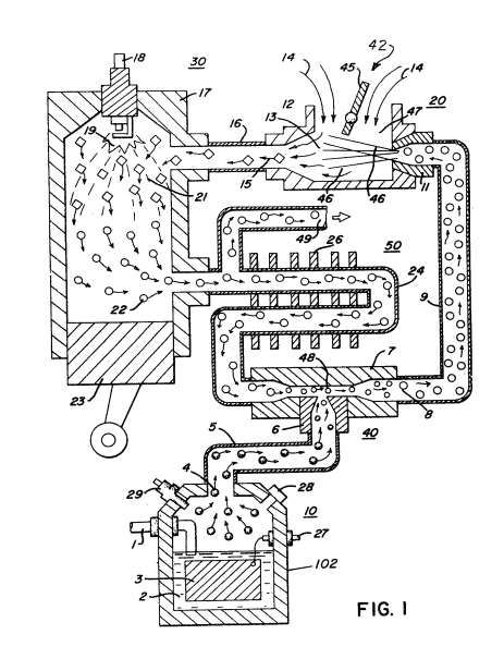
The output of gases from mixing chamber 40 as described relative to Figure 1 and 2 is fed via line 9 to an air/gas mixture system 42. In this instance, the intake air 14 may be in a carburetor arrangement with an intake adjustment 55 that adjusts a plate on an air intake opening of the air/gas mixture system 42. The gas mixture is fed into the carburetor by nozzle 11 and mixed with the air 14.
How it is written
- (air 14) 3×
- (intake air 14) 1×
Drawings 1
-
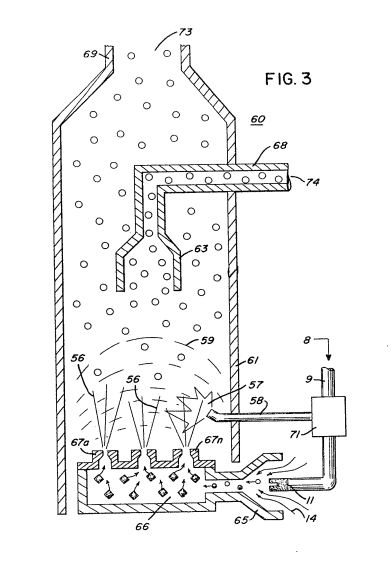
With particular reference to Figure 3 there is illustrated an alternative combustion chamber 60 that may be utilized in lieu of the chamber 30 of Figure l. · Hydrogen Injection System
Where it is named · 4
Hydrogen Injection System 4×
-
intake air (intake air 14)
The output of gases from mixing chamber 40 as described relative to Figure 1 and 2 is fed via line 9 to an air/gas mixture system 42. In this instance, the intake air 14 may be in a carburetor arrangement with an intake adjustment 55 that adjusts a plate on an air intake opening of the air/gas mixture system 42. The gas mixture is fed into the carburetor by nozzle 11 and mixed with the air 14.
-
air (air 14)
The output of gases from mixing chamber 40 as described relative to Figure 1 and 2 is fed via line 9 to an air/gas mixture system 42. In this instance, the intake air 14 may be in a carburetor arrangement with an intake adjustment 55 that adjusts a plate on an air intake opening of the air/gas mixture system 42. The gas mixture is fed into the carburetor by nozzle 11 and mixed with the air 14.
-
air (air 14)
… There the gas mixture is further mixed with air 14 to form combustible gas- The gas/air mixture is dispersed via ports 67a XXX 67n from the dispersing chamber 66 into the firing area of the combustion chamber 60. …