(40)
Chamber
Where it is first named
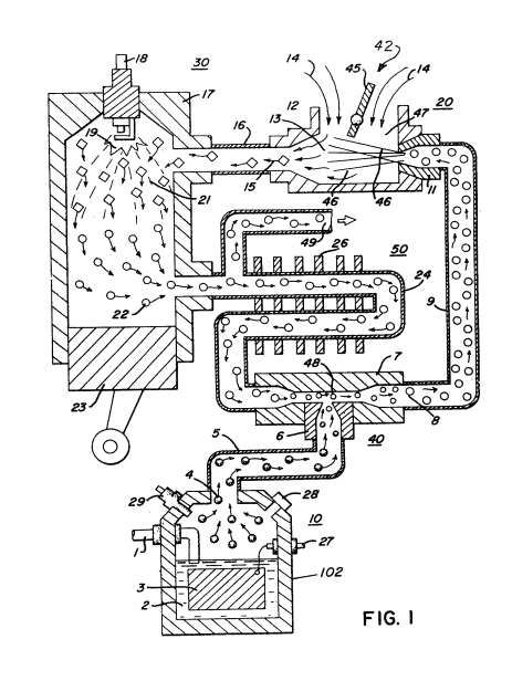
The exhaust gases 22, the residue of the combustion 21, now comprises a non-combustible mixture. These exhaust gases 22 are fed via pipe line 24 to the gas mixing chamber 40 as the non-combustible gases as aforesaid.
How it is written
- (chamber 40) 7×
Drawings 3
-
To replenish the expended water the generator is connected via line 1 to a suitable water source. · Hydrogen Injection System
-
Carries this number · Hydrogen Injection System
-
The figure it sits on · Hydrogen Injection System
Where it is named · 7
Hydrogen Injection System 7×
-
chamber (chamber 40)
The exhaust gases 22, the residue of the combustion 21, now comprises a non-combustible mixture. These exhaust gases 22 are fed via pipe line 24 to the gas mixing chamber 40 as the non-combustible gases as aforesaid.
-
chamber (chamber 40)
The pipe line 24 passes through cooling chamber 50 for cooling of the gases therein. The cooling chamber 50 also functions as a spark arrestor to eliminate the possibility of gas ignition inside the mixing chamber 40. The excess non-combustible gases are exhausted via outlet 4g, to be expelled into the atmosphere.
-
chamber (chamber 40)
The outlet 5 on the generator 10 receives the combustible and non-combustible (oxygen and nitrogen) gases generated thereby and feeds the same to the mixing chamber 40. The flow of the hydrogen gas is, of course; critical; therefore, there is incorporated in line 5 a gas flow valve 53 (Fig. 2) to adjust the hydrogen flow.
-
chamber (chamber 40)
The exhaust gases 22 are fed via inlet pipe 31 to the cooling and spark arrestor chamber 50 and by pipe 24 into the mixing chamber 40. These gases from cooling and spark arrestor chamber 50 to mixing chamber 40 are controlled by a flow control valve 51 in pipe line 24.
-
chamber (chamber 40)
The exhaust gases 22 are fed via inlet pipe 31 to the cooling and spark arrestor chamber 50 and by pipe 24 into the mixing chamber 40. These gases from cooling and spark arrestor chamber 50 to mixing chamber 40 are controlled by a flow control valve 51 in pipe line 24.
-
chamber (chamber 40)
The output of gases from mixing chamber 40 as described relative to Figure 1 and 2 is fed via line 9 to an air/gas mixture system 42. In this instance, the intake air 14 may be in a carburetor arrangement with an intake adjustment 55 that adjusts a plate on an air intake opening of the air/gas mixture system 42. The gas mixture is fed into the carburetor by nozzle 11 and mixed with the air 14.
-
chamber (chamber 40)
Gas regulator valve 75 is utilized to reduce the pressure level inside hydrogen generator 10. The pressure differential hydrogen gas output to gas mixing chamber 40 is, for example, 30 lbs. …