Figure (2)
Figure (2)
How it is written
- (2) 4×
Drawings 1
-
Captioned as this figure · Hydrogen Injection System
On this figure 2
Where it is named · 4
Hydrogen Injection System 4×
-
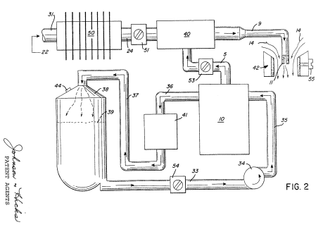
Figure 2 is a block schematic illustration of the preferred embodiment of Figure 1;
-
Similarly, Figure 2 illustrates the complete system in its preferred embodiment.
-
The apparatus of Figure 2 comprises much the same system as Figure 1. In this embodiment the components are depicted more explicitly in their structural relationship in an alternate arrangement. Basically, the system is operable as that in Figure 1, i-e. a mixture of combustible (hydrogen) gas and non-combustible gases (exhaust).
-
The outlet 5 on the generator 10 receives the combustible and non-combustible (oxygen and nitrogen) gases generated thereby and feeds the same to the mixing chamber 40. The flow of the hydrogen gas is, of course; critical; therefore, there is incorporated in line 5 a gas flow valve 53 (Fig. 2) to adjust the hydrogen flow.