Figure (4)
Figure (4)
How it is written
- (4) 2×
Drawings 1
-
The major portion of the non-combustible gases by-pass the cone 63 and rise further to the outlet exhaust 69 and are expelled at opening 73. · Hydrogen Injection System
Where it is named · 2
Hydrogen Injection System 2×
-
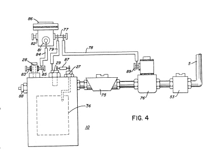
Figure 4 is a block schematic illustration of a complete drive system utilizing the concepts of the present invention;
-
In the constructed arrangement of Figure 4, there is illustrated a gas control system that may be retrofitted to an existing automobile internal combustion engine without changing or modifying its design parameters or characteristics.