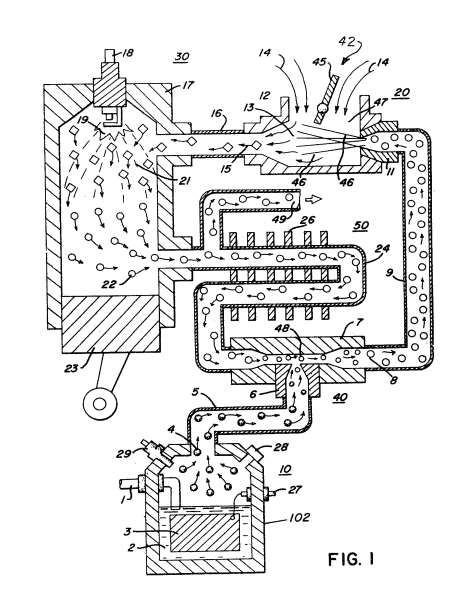
Figure (1)
Figure (1)
How it is written
- (1) 10×
Drawings 1
-
To replenish the expended water the generator is connected via line 1 to a suitable water source. · Hydrogen Injection System
On this figure 15
- 10 Generator
- 14 Air
- 18 Spark Plug Igniter
- 22 Exhaust Gases
- 40 Chamber
- 42 Gas Mixture System
- 55 Intake Adjustment
- 57 Pilot Light Combustion
- 59 Combustion
- 60 Combustion Chamber
- 63 Cone
- 66 Chamber
- 74 Outlet
- 95 Alternator
- 102 Container
Where it is named · 10
Hydrogen Injection System 10×
-
Figure 1 is a schematic cross-sectional illustration of one embodiment of the present invention;
-
Figure 2 is a block schematic illustration of the preferred embodiment of Figure 1;
-
Figure 3 is an alternative gas system replacement for that shown in Figure 1;
-
Figure 1 illustrates a complete overall combustion system together with a piston and cylinder of an internal combustion engine.
-
With particular reference to Figure 1, the hydrogen source 10 is the hydrogen generator disclosed and described in my co-pending application, supra. …
-
The apparatus of Figure 2 comprises much the same system as Figure 1. In this embodiment the components are depicted more explicitly in their structural relationship in an alternate arrangement. Basically, the system is operable as that in Figure 1, i-e. a mixture of combustible (hydrogen) gas and non-combustible gases (exhaust).
-
The apparatus of Figure 2 comprises much the same system as Figure 1. In this embodiment the components are depicted more explicitly in their structural relationship in an alternate arrangement. Basically, the system is operable as that in Figure 1, i-e. a mixture of combustible (hydrogen) gas and non-combustible gases (exhaust).
-
The output of gases from mixing chamber 40 as described relative to Figure 1 and 2 is fed via line 9 to an air/gas mixture system 42. In this instance, the intake air 14 may be in a carburetor arrangement with an intake adjustment 55 that adjusts a plate on an air intake opening of the air/gas mixture system 42. The gas mixture is fed into the carburetor by nozzle 11 and mixed with the air 14.
-
… As the non-combustible gases (exhaust gases 22 of Figure 1) rise upwardly in the cylinder 61, of the combustion chamber 60 the cone 63 captures a portion of such non-combustible gases. …
-
… In operation, the process mixture is ignited much in the same manner as in Figure 1. …