(53)
Flow Adjustment Valve
Also written gas flow valve
Where it is first named
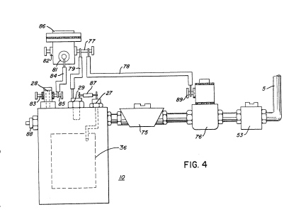
The outlet 5 on the generator 10 receives the combustible and non-combustible (oxygen and nitrogen) gases generated thereby and feeds the same to the mixing chamber 40. The flow of the hydrogen gas is, of course; critical; therefore, there is incorporated in line 5 a gas flow valve 53 (Fig. 2) to adjust the hydrogen flow.
How it is written
- (flow adjustment valve 53) 1×
- (gas flow valve 53) 1×
Drawings 2
-
The major portion of the non-combustible gases by-pass the cone 63 and rise further to the outlet exhaust 69 and are expelled at opening 73. · Hydrogen Injection System
-
The figure it sits on · Hydrogen Injection System
Where it is named · 2
Hydrogen Injection System 2×
-
gas flow valve (gas flow valve 53)
The outlet 5 on the generator 10 receives the combustible and non-combustible (oxygen and nitrogen) gases generated thereby and feeds the same to the mixing chamber 40. The flow of the hydrogen gas is, of course; critical; therefore, there is incorporated in line 5 a gas flow valve 53 (Fig. 2) to adjust the hydrogen flow.
-
flow adjustment valve (flow adjustment valve 53)
As low-voltage direct current is applied to safety valve 28, solenoid 86 is activated. This results in applying a control voltage to the hydrogen generator plates 3 via terminal 27 through pressure switch 29. Hydrogen gas produced in hydrogen generator 10 passes through flow adjustment valve 53 and then outlet pipe 5 for utilization.