(20)
Chamber
Also written system
Where it is first named
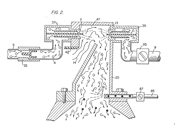
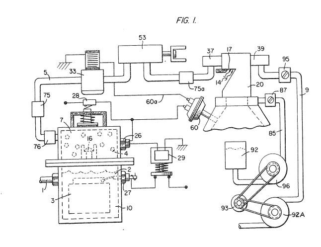
… With particular reference to Figure 2 the hydrogen gas via pipe line 5 and non-combustible gasses via pipe line 9 are fed to a carburetor (air-mixture) system 20 also having an ambient air intake 14. The hydrogen gas 4 is fed via line 5 through nozzle 11 in a spray into the trap area 47 of the mixing chamber 20. Nozzle 11 has an opening smaller than the
How it is written
- (chamber 20) 10×
- (system 20) 1×
Drawings 5
-
Carries this number · Hydrogen Gas Injection for Internal Combustion Engine
-
Carries this number · Hydrogen Gas Injection for Internal Combustion Engine
-
Carries this number · Hydrogen Gas Injection for Internal Combustion Engine
-
Carries this number · Hydrogen Gas Injection for Internal Combustion Engine
-
Carries this number · Hydrogen Gas Injection for Internal Combustion Engine
Where it is named · 11
Hydrogen Gas Injection for Internal Combustion Engine 11×
-
system (system 20)
… With particular reference to Figure 2 the hydrogen gas via pipe line 5 and non-combustible gasses via pipe line 9 are fed to a carburetor (air-mixture) system 20 also having an ambient air intake 14. The hydrogen gas 4 is fed via line 5 through nozzle 11 in a spray into the trap area 47 of the mixing chamber 20. Nozzle 11 has an opening smaller than the
-
chamber (chamber 20)
… The hydrogen gas 4 is fed via line 5 through nozzle 11 in a spray into the trap area 47 of the mixing chamber 20. Nozzle 11 has an opening smaller than the
-
chamber (chamber 20)
plate openings in the quenching assembly 37, thereby preventing flash back in the event of sparking. The non-combustable gasses are injected into mixing chamber 20 trap area in a jet spray via nozzle 13. Quenching assembly 39 is operable much in the same manner as quenching assembly 37.
-
chamber (chamber 20)
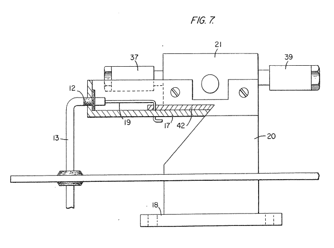
Referring now to Figures 7 and 8 there is illustrated the air adjustment control for manipulating the amount of air passing into the mixing chamber 20. …
-
chamber (chamber 20)
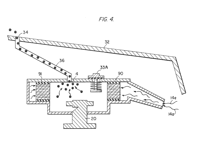
With reference now to Figure 4, in the event hydrogen gas 4 should accumulate in the mixing chamber 20 to excessive pressure, an escape tube 36 connected to a port 34 on the automobile hood 32 permits the excess hydrogen gas to safely escape to the atmosphere. …
-
chamber (chamber 20)
… The pressure differential hydrogen gas output to gas mixing chamber 20 is for example 30 lbs. …
-
chamber (chamber 20)
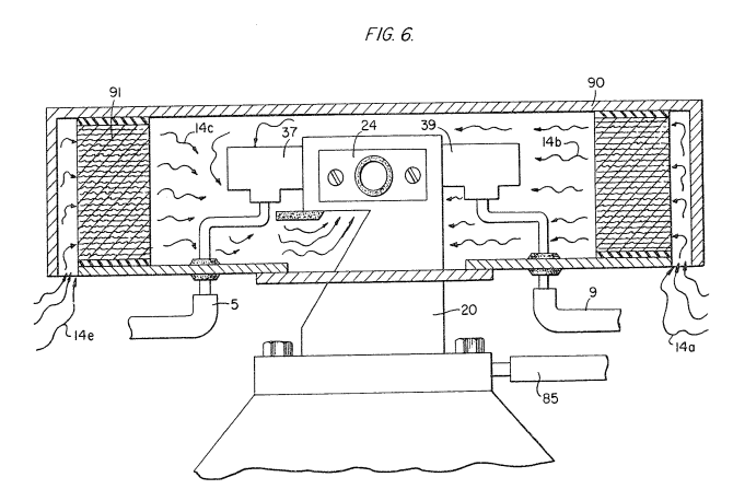
… The air passes through filter 91 as indicated at 14b and 14c around the components and then to intake 17 of the mixing chamber 20. …
-
chamber (chamber 20)
… The hydrogen enters via line 5 via quenching plates in the quenching assembly 37 and into the mixing chamber 20. The non-combustible gasses pass via line 9 to the quenching plates of the quenching assembly 39 and into the mixing chamber 20.
-
chamber (chamber 20)
… The non-combustible gasses pass via line 9 to the quenching plates of the quenching assembly 39 and into the mixing chamber 20.
-
chamber (chamber 20)
Figure 7 illustrates the mechanical arrangement of components comprising the overall structure of the mixing chamber 20 and shown independently in the other figures.
-
chamber (chamber 20)
Also driven by pulley 93 is pump 96 having line 85 connected to an oil reservoir 92 and valve 87 and finally to mixing chamber 20. As a practical matter, such as in a non-oil lubricated engine, lubricating fluid such as oil 81 is sprayed in the chamber 20, via oil supply line 85 for lubrication.