

Figure (20D)
Power Load Distribution Copyright
How it is written
- (20D) 7×
Drawings 1
-
Figure 20D · Resonant Cavity
On this figure 1
Where it is named · 7
Resonant Cavity 3×
-
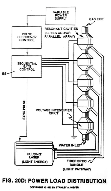
6. Said variable gate circuit (55) of Figure 20D is now retrofitted to said dual-pulsing circuit 20C to extend gas production beyond the limits of a single resonant cavity, keeping power loading to a minimum while adding another gas control feature.
-
Figure 20D
-
7. As shown in Figure 20D, said resonant cavities are stacked exit port to inlet port to accelerate said compounding-action per stage.
Operational Comments 2×
-
Said ionized gases enter into other resonant cavities (see Figure 20D as to Figure 20C again) in stacked relationship (exit port to inlet port) undergoing the same gas ionization process.
Resonant Cavity Mode of Operability 2×
-
To increase gas yield still further, said ionized or charged particles of gases are now injected into other resonant cavities undergoing above said resonant action process (see Figure 20D as to Figure 20C).
-
Figure 20D