(10)
Particle Accelerator
Also written magnetic particle accelerator
Where it is first named
Figure 6 illustrates a concentric spiral configuration of the tubing 50 having the secondary windings 53 wound over it's entirety. In Figure 7 the particle accelerator 10 is wound over the tubing 30 much in the same manner as the Figures 1 and 2.
How it is written
- (particle accelerator 10) 2×
- (magnetic particle accelerator 10) 1×
Drawings 3
-
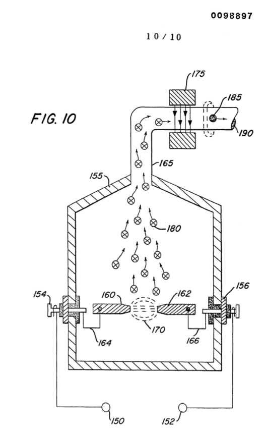
Figure 10 is a mechanical illustration of a magnetic particle generator for developing magnetic particles utilized in the present invention. · Electrical Generator Utilizing Magnetized Particles
-
Figure 7 is another alternative arrangement in a preferred illustration of the invention. · Electrical Generator Utilizing Magnetized Particles
-
The figure it sits on · Electrical Generator Utilizing Magnetized Particles
Where it is named · 3
Electrical Generator Utilizing Magnetized Particles 3×
-
magnetic particle accelerator (magnetic particle accelerator 10)
The magnetic particle accelerator 10 may comprise configurations and structures distinctive from the electrical accelerator of Figure 1. …
-
particle accelerator (particle accelerator 10)
In the simplified preferred embodiment of Figures 1 and 2, as well as the referred preferred embodiments it was indicated that a low voltage was applied to the particle accelerator 10. …