Figure (7)
Figure (7)
How it is written
- (7) 3×
Drawings 1
-
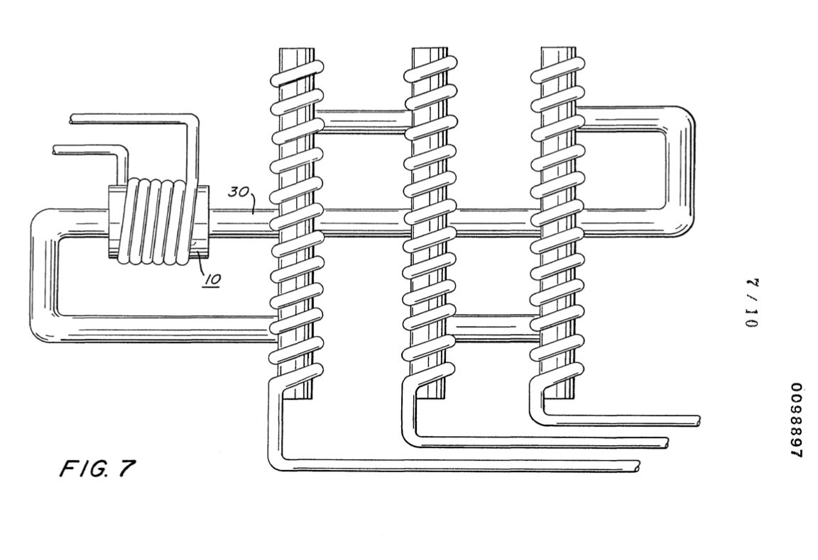
Figure 7 is another alternative arrangement in a preferred illustration of the invention. · Electrical Generator Utilizing Magnetized Particles
On this figure 6
Where it is named · 3
Electrical Generator Utilizing Magnetized Particles 3×
-
Figure 7 is another alternative arrangement in a preferred illustration of the invention.
-
Figure 6 illustrates a concentric spiral configuration of the tubing 50 having the secondary windings 53 wound over it's entirety. In Figure 7 the particle accelerator 10 is wound over the tubing 30 much in the same manner as the Figures 1 and 2.
-
… In Figure 8 the reverse of that configuration of Figure 7 is shown. …