(12)
Terminals
Also written input terminals
Where it is first named
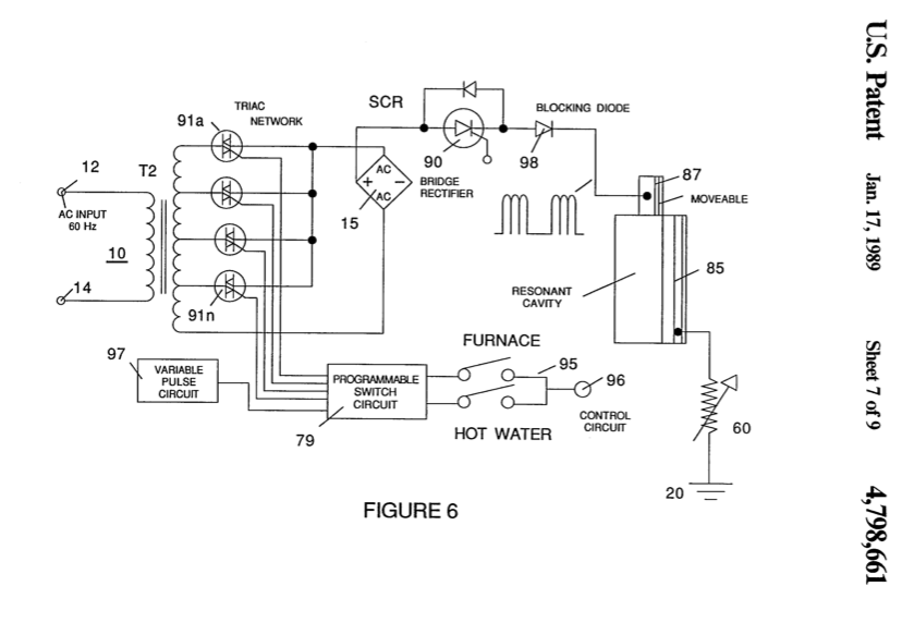
The alternating current rectifier circuit 10 comprises input alternating current terminals 12 and 14. Switch 13 is a typical on/off switch. Transformer 10 is an inductive primary and secondary transformer connected to a bridge rectifier 15. The inductive field 11 of the transformer 10 is variable in a known manner to yield a variable frequency alternating voltage/current to the primary winding.
How it is written
- (terminals 12) 2×
- (input terminals 12) 1×
Drawings 2
-
Carries this number · Gas Generator Voltage Control Circuit
-
In FIG. 4A and 4B, the frequency of the pulsed d.c. voltage is matched to the distance in wavelengths of the plate exciters. · Gas Generator Voltage Control Circuit
Where it is named · 3
Gas Generator Voltage Control Circuit 3×
-
terminals (terminals 12)
The alternating current rectifier circuit 10 comprises input alternating current terminals 12 and 14. Switch 13 is a typical on/off switch. Transformer 10 is an inductive primary and secondary transformer connected to a bridge rectifier 15. The inductive field 11 of the transformer 10 is variable in a known manner to yield a variable frequency alternating voltage/current to the primary winding.
-
terminals (terminals 12)
… The rectifier inverts the negative swing of the alternating current and thereby results in an output voltage pulse of a frequency twice that of the input frequency of the alternating current voltage applied to the terminals 12 and 14.
-
input terminals (input terminals 12)
The frequency of the pulsed d.c. voltage may be altered by an alternating current of another frequency applied to the input terminals 12 and 14. Alternatively, the frequency of the pulsed d.c. voltage may be varied as shown by the variable transformer 10 winding 11.